Quantcast
Need electrical help with car racing sim. - Beyond.ca - Car Forums
Page 1 of 2 1 2 LastLast
Results 1 to 20 of 26

Thread: Need electrical help with car racing sim.

  1. #1
    Join Date
    Mar 2005
    Location
    Calgary
    My Ride
    ...
    Posts
    797
    Rep Power
    20

    Default Need electrical help with car racing sim.

    I'm far from an electricial and am in need of some assistance from someone who has some knowledge in wiring. I am building a racing sim for live for speed, rfactor and gran turismo 5 prologue... The pedals, shifter, steering wheel, dash and ebrake are all setup and working.. I'm at the point where I want to install some LED lighting and use the factory headlamp on/off switch for a couple things... To be an on/off switch for the LED's and to send a signal to the remote wire on the cd-deck so it turns on.

    I have managed to get a wiring diagram from someone at vwvortex as to what the pin outs on the switch do..

    Wiring Diagram - Click Here

    If possible I would also like to light up the backlit part of the dash buttons and use the dimmer to dim the dash buttons and the interior LED's.

    I know for LED's your not supposed to just lower voltage, you should be using pusle modulation... I don't know which one the factory VW switch does, i'm assuming it's LED's that are used in the backlit dash buttons and switches.

    Is this possible?

    Thanks.

  2. #2
    Join Date
    Mar 2005
    Location
    Calgary
    My Ride
    ...
    Posts
    797
    Rep Power
    20

    Default

    Preview pic:


  3. #3
    Join Date
    May 2006
    Location
    Calgary
    My Ride
    2001 &2003 TOYOTA Soarer Convertible
    Posts
    389
    Rep Power
    18

    Default

    sorry I can not help you out but I just want to say
    you got a heck of a serious rig for racing sim man....
    the best I can do for my rig is 3 of 22 inches monitor and a racing wheel on my table....
    your rig gives me some idea to do this summer....

  4. #4
    Join Date
    Apr 2004
    Location
    Calgary
    My Ride
    1985 300ZX
    Posts
    79
    Rep Power
    0

    Default

    First let me say that is sweet!

    Why are you using LED to light it...is that what the back lighting all ready has? if it was me I would stick with what ever lights were there (probably 12v bulbs) and just use a decent regulated 12v power supply.

    Have you considered putting an audio deck back in? would probably require another separate power supply but would be sweet!
    Speedy
    1985 300ZX & 1991 300ZX

  5. #5
    Join Date
    Apr 2008
    Location
    Calgary
    My Ride
    missy
    Posts
    1,792
    Rep Power
    20

    Default

    wow, thats impressive - cant help either but wow
    CNC Guru*

    * This is not an advertisement or porn..... but pm me lol

    Instagram: goreski_rdd

  6. #6
    Join Date
    Mar 2005
    Location
    Calgary
    My Ride
    ...
    Posts
    797
    Rep Power
    20

    Default

    Originally posted by Speedy
    First let me say that is sweet!

    Why are you using LED to light it...is that what the back lighting all ready has? if it was me I would stick with what ever lights were there (probably 12v bulbs) and just use a decent regulated 12v power supply.

    Have you considered putting an audio deck back in? would probably require another separate power supply but would be sweet!
    I don't know what type of bulbs are used in the backlighting on the dash buttons... I don't want to use 12v bulbs because of the heat.. I want to go with LED lighting since the inside is carpeted...

    I will be putting in a pioneer deck with bluetooth for audio with four speakers and a sub.. I will have a seperate 13.8V 10a power supply for that... the sub will be a home audio amplified sub.. so just need to run the rca from the deck to the sub after. I will then have seperate volume for music and gaming..

    It's still far from complete but it's slowly getting there. I still need to find a good deal on a matching set of momo wheel, shift knob, e-brake handle and pedals.. then a nice racing seat. recaro or bride or something... it should be done in a month or two.

  7. #7
    Join Date
    Mar 2005
    Location
    Calgary
    My Ride
    ...
    Posts
    797
    Rep Power
    20

    Default

    Here's a video of the screens working.. Still needing help with electrical and that switch.


  8. #8
    Join Date
    Jun 2006
    Location
    Calgary
    Posts
    2,452
    Rep Power
    20

    Default

    LEDs just run on normal DC voltage. You can use a potentiometer(an adjustable resistor) for dimming them. LEDs need to be "forward biased" which means voltage must be applied to them in correct polarity (negative to negative, positive to positive). They have a "on" voltage, this is the voltage that must be applied to the LED before it turns "on" and starts to conduct current. The operating voltage for the LED will usually be stated on the package the LEDs come in.


    Now if you hook up a LED backwards, and crank up the voltage it will hit it's "breakdown region" and fry the LED. So always make sure polarity is correct.

    What's the easiest and least mind numbing way to hook up LEDs? Personally using a power supply like 12Vs, and hooking them up in parallel with a resistor in series with each LED to reduce the voltage for each LED so you don't fry them.

    I can sketch out a sample wiring diagram that could work for your setup if you wish.
    Last edited by Cooked Rice; 05-09-2008 at 01:09 AM.

  9. #9
    Join Date
    Feb 2005
    Location
    Calgary
    My Ride
    broken POS
    Posts
    334
    Rep Power
    20

    Default

    WOW just wow that is amazing, crazy work man crazy...

  10. #10
    Join Date
    Mar 2005
    Location
    Calgary
    My Ride
    ...
    Posts
    797
    Rep Power
    20

    Default

    Originally posted by Cooked Rice
    LEDs just run on normal DC voltage. You can use a potentiometer(an adjustable resistor) for dimming them. LEDs need to be "forward biased" which means voltage must be applied to them in correct polarity (negative to negative, positive to positive). They have a "on" voltage, this is the voltage that must be applied to the LED before it turns "on" and starts to conduct current. The operating voltage for the LED will usually be stated on the package the LEDs come in.


    Now if you hook up a LED backwards, and crank up the voltage it will hit it's "breakdown region" and fry the LED. So always make sure polarity is correct.

    What's the easiest and least mind numbing way to hook up LEDs? Personally using a power supply like 12Vs, and hooking them up in parallel with a resistor in series with each LED to reduce the voltage for each LED so you don't fry them.

    I can sketch out a sample wiring diagram that could work for your setup if you wish.
    Ok so with a potentiometer I heard it's hard on the LED's and they will not all be the same brightness.. thats why I heard your supposed to use that pulse modulator so it basically makes the LEDs blink so fast you cannot see it.. I also heard it will extend the lifespan of the LEDs if done this way.

    I will have 13.8V of power in the car sim to power the deck. I can take power from there or buy a seperate 12v power supply. I'm sure I can get 8-10 LED's to light up with an on off switch, its the intergration of the cars headlamp switch that throws me off a little.. and using that switch to power the remote wire from the deck... so you get in the car sim, flick on the headlamp and your LED's light up and your deck comes on. If you would be able to draw out something like that it would be SUCH a huge help

    Thank you all for you help and comments

  11. #11
    Join Date
    Jun 2006
    Location
    Calgary
    Posts
    2,452
    Rep Power
    20

    Default

    So in this diagram we will be using Red LEDs rated at 2 Volts forward voltage each @ a current draw of 20mA each.


    Okay so our goal here is to supply 2 volts to each LED. And when that happens the LED should draw aprox. 20mA from the power supply. Your power supply is probably at least a few amps, so we shouldn't have to worry about the Amperage.


    Okay so the power source gives out 13.8 volts. We need to reduce that so each LED gets 2 volts. We will use individual resistors to do this.


    When wiring in parallel each of the parallel loads will be supplied with the SAME voltage as the SOURCE voltage. That means the voltage across BOTH LED and Resistor in each "bank" will equal 13.8 Volts. -BUT remember the LEDs only want 2 volts each. So what do we do? We chose a correct resistors to soak up the other 11.8 volts. 13.8 - 2 = 11.8


    Okay so lets calculate what each resistor has to be using ohms law:

    Resistance = voltage/current

    Okay voltage, how much voltage do we want the resistor to "soak" up? 11.8V

    Now current, how much current is going to be going through the "bank"? Well current is the same for each load within a series type circuit. And in each "bank" the LED and resistor are in "series". So remember how much the LEDs drew? 20mA.

    So lets calculate:

    R=V/I(current)

    11.8v/20mA = 590 Ohms of resistance.

    But 590 ohm resistors are uncommon, so you use the closest ones: 560 or 520.

    There you go, you will need 590 ohms of resistance to supply the LED with 2 volts.

    The beauty of parallel circuits?
    You can have as MANY "banks" of the SAME LEDs and they will all use the SAME resistance values per each resistor.

    Now in the drawing you see a pot (adjustable resistor). You can find these in all sorts of resistance values. Connect it in series with the battery before your parallel banks and you can adjust the amount of voltage the "banks" each receive. Good values are 0 to 1K ohms pots you can go higher if you want to dim them even more. Make sure the pots are rated for at least 1W so they don't overheat.

    Even though the LEDs may be rated for 2Vs, and you supply them with less than 2V they will still dim. Until the voltage gets too low.

    I finished my first year of aircraft avionics(basically aircraft electricians) at sait this year, so that is where I get most of my knowledge from. I know n1zmo on here is a 2nd year graduate, and he could probably correct me if I made any mistakes. But i'm pretty sure it's correct since this is rather basic stuff compared to the other things we learn/do.
    Last edited by Cooked Rice; 05-09-2008 at 10:46 PM.

  12. #12
    Join Date
    Mar 2005
    Location
    Calgary
    My Ride
    ...
    Posts
    797
    Rep Power
    20

    Default

    I totally appreciate and understand what your saying for hooking up the LED's but my main problem is still the integration to the headlight on off switch that I linked the picture of in my first post.

    The switch is much more than an on/off switch... it has 17 connections on the bottom of it. Once I have my string of LED's lit up and ready to power like in your diagram above I need to either hook it up directly through the headlamp on/off switch or have the headlamp switch run some sort of a relay that can be attached to an on/off switch.

    Also with regards to the 0-1K pot.. The stock VW dimmer is a pot as well - i just don't know what its rated at or what of the 3 wires do what, i need to find out somehow if that stock dimmer can dim the LED's if possible.

    Thanks again for all the help, I really do appreciate and need it :P This project turned out being a little bigger than first planned.

  13. #13
    Join Date
    Jun 2004
    Location
    Calgary, Alberta
    My Ride
    90 DB1, 03 RL1, 07 YK1
    Posts
    2,609
    Rep Power
    22

    Default

    Nice work!

    Calgary is so much like an iphone: iCalgary - There's a bylaw for that.

  14. #14
    Join Date
    Dec 2006
    Location
    Calgary
    My Ride
    is Turbocharged.
    Posts
    366
    Rep Power
    18

    Default

    damn thats sick... I play lfs and I want a station like that haha

  15. #15
    Join Date
    Jun 2006
    Location
    Calgary
    Posts
    2,452
    Rep Power
    20

    Default

    Usually automotive pots will be close to 0 ohms resistance and higher. So you don't have to worry about the LEDs not being "bright" enough. As for the pot, you should be able to use 2 of the 3 wires. Usually the middle one and either one of the outer wires. We used pots in school which had 3 leads and that's how they worked.

    You connect the middle one and one of the outer ones. The reason some pots have 3 leads is so you can:

    Have FULL resistance when turned 'fully counter clockwise'.

    or hook up the opposite lead:

    And have LEAST resistance when turned 'fully counter clockwise' and vise versa.

  16. #16
    Join Date
    Oct 2004
    Location
    AB/NS
    Posts
    3,284
    Rep Power
    24

    Default

    0 ohms and higher eh? thats makes a lot of sense.

  17. #17
    Join Date
    May 2004
    Location
    Far Away
    My Ride
    CRF 250L
    Posts
    152
    Rep Power
    0

    Default

    to the OP:

    Nice Rig!

    Originally posted by Supa Dexta
    0 ohms and higher eh? thats makes a lot of sense.
    0 Ohms and Up.....

    When you turn it to 0, its 0 Ohms.


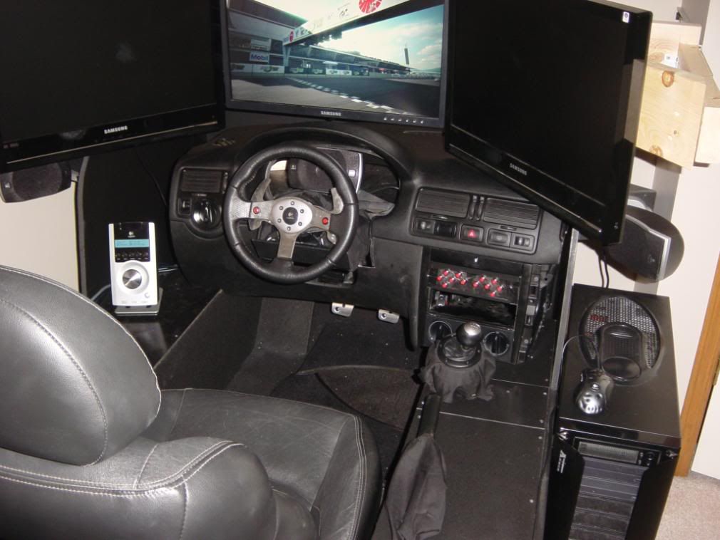
    OP Says:I'm far from an electricial and am in need of some assistance from someone who has some knowledge in wiring. I am building a racing sim for live for speed, rfactor and gran turismo 5 prologue... The pedals, shifter, steering wheel, dash and ebrake are all setup and working.. I'm at the point where I want to install some LED lighting and use the factory headlamp on/off switch for a couple things... To be an on/off switch for the LED's and to send a signal to the remote wire on the cd-deck so it turns on.

    I have managed to get a wiring diagram from someone at vwvortex as to what the pin outs on the switch do..


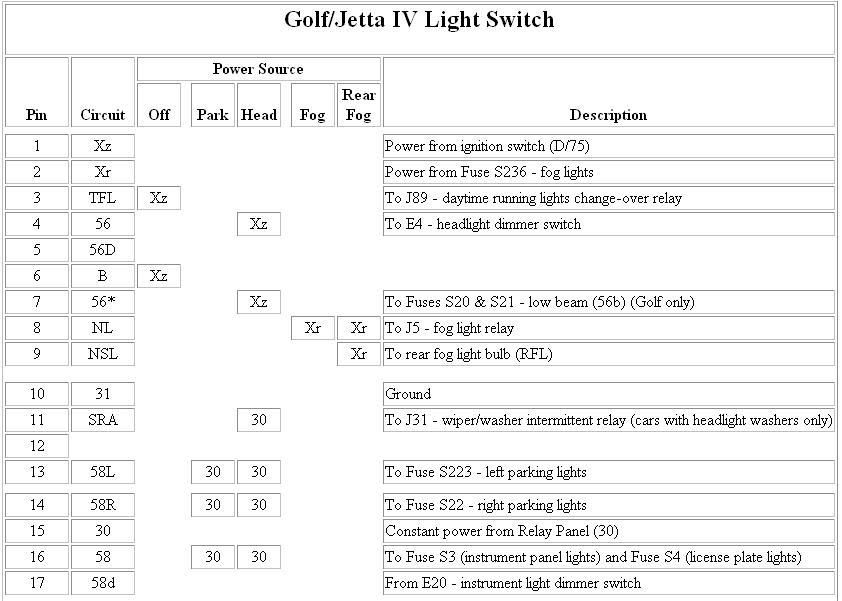
    To me it looks pretty straight forward.

    Your light switch has 5 settings Off, Park, Head, Fog, and Fog Rear.

    The diagram shows on each setting fo the switch, which pins will be connected to which circuits of your vehicle.


    What you'd have to do is figure out what you want to turn on at what switch point and then splice into the circuits listed Xr, Xz, 30 etc...


    EDIT: maybe a simpler way to look at it would be that when you set it to 'Park', Pins 13,14,16 will be connected to pin 15.

    When you have it on 'Fog', pin1 gets connected to Pin 8 etc...
    Last edited by broken_legs; 05-10-2008 at 04:31 PM.
    TRUTH: it's the new hate speech.
    In a time of universal deceit - telling the truth is a revolutionary act. - Orwell

  18. #18
    Join Date
    Oct 2004
    Location
    AB/NS
    Posts
    3,284
    Rep Power
    24

    Default

    haha I know how a pot works. My point was "0 ohms and higher" what else is it going to be? 0 ohms and negative 50 ohms? I've been drinking, I thought it was funny in my head.

  19. #19
    Join Date
    May 2004
    Location
    Far Away
    My Ride
    CRF 250L
    Posts
    152
    Rep Power
    0

    Default

    Originally posted by Supa Dexta
    haha I know how a pot works. My point was "0 ohms and higher" what else is it going to be? 0 ohms and negative 50 ohms? I've been drinking, I thought it was funny in my head.
    At first I was on your side, but the more I thought about the simplicity of the comment, I began to realize it was brilliant.
    TRUTH: it's the new hate speech.
    In a time of universal deceit - telling the truth is a revolutionary act. - Orwell

  20. #20
    Join Date
    Nov 2002
    Location
    Calgary
    Posts
    196
    Rep Power
    0

    Default

    props
    When lazy let idle.

Page 1 of 2 1 2 LastLast

Similar Threads

  1. FS: Fido sim card, rogers sim card and leather razr case

    By G-ZUS in forum Cellular Products
    Replies: 0
    Latest Threads: 09-25-2007, 06:01 PM
  2. In Need Of Some Serious Electrical Help!

    By dam_guy in forum Mechanical
    Replies: 13
    Latest Threads: 06-01-2007, 03:40 PM
  3. FS: New Rogers Sim Card and New Fido Sim Card

    By c001m4n in forum Cellular Products
    Replies: 2
    Latest Threads: 04-05-2005, 01:41 PM
  4. FS- Racing wheel,racing seats, racing harness's

    By PiMpIn SmUrF in forum Automotive Parts [Aero/Styling/Interior]
    Replies: 6
    Latest Threads: 01-31-2005, 03:04 PM
  5. Crown Victori PP Need Electrical Help

    By CVPP in forum Mechanical
    Replies: 3
    Latest Threads: 01-22-2003, 05:06 PM

Posting Permissions

  • You may not post new threads
  • You may not post replies
  • You may not post attachments
  • You may not edit your posts
  •