speechless....

 Registered User

speechless....
Registered User

Well, I'm STILL waiting on valve shims, they didn't come in today. The parts guy forgot to order them on my long grocery list I guess, so the engine sits unfinished... Piss me off! Anyway, I decided to bolt up what I could.
Bolted on the water neck, thermostat housing, water pump, A/C bracket...
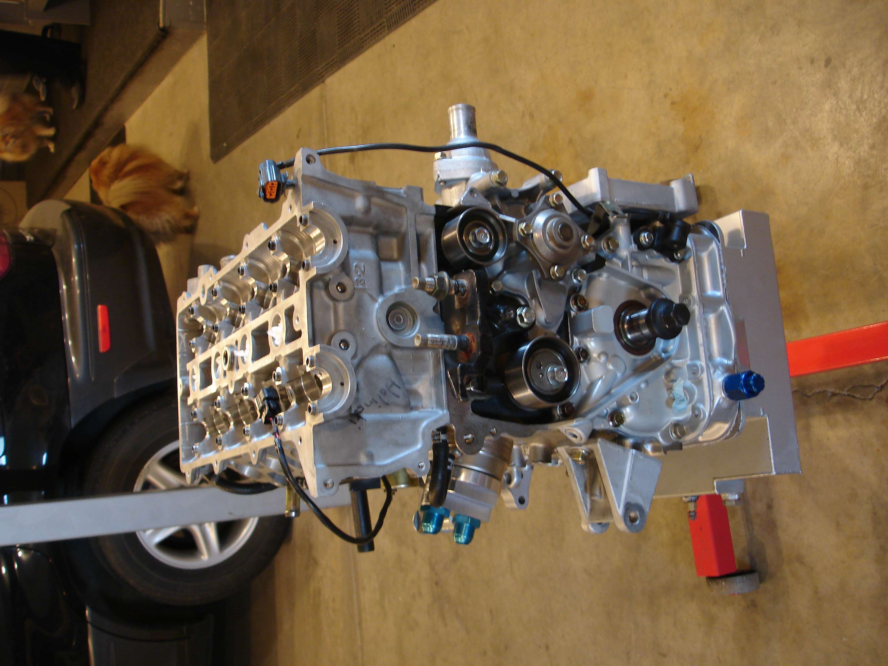
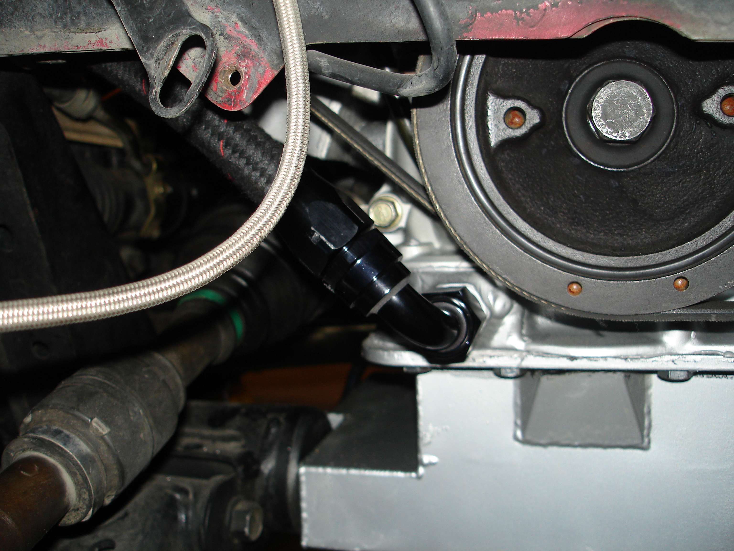
Timing belt tensioner and pulley, crank position sensor...
And on the backside, the oil to water MSP oil cooler, alternator bracket, knock sensor, oil pressure sender, and oil filter adapter plate.
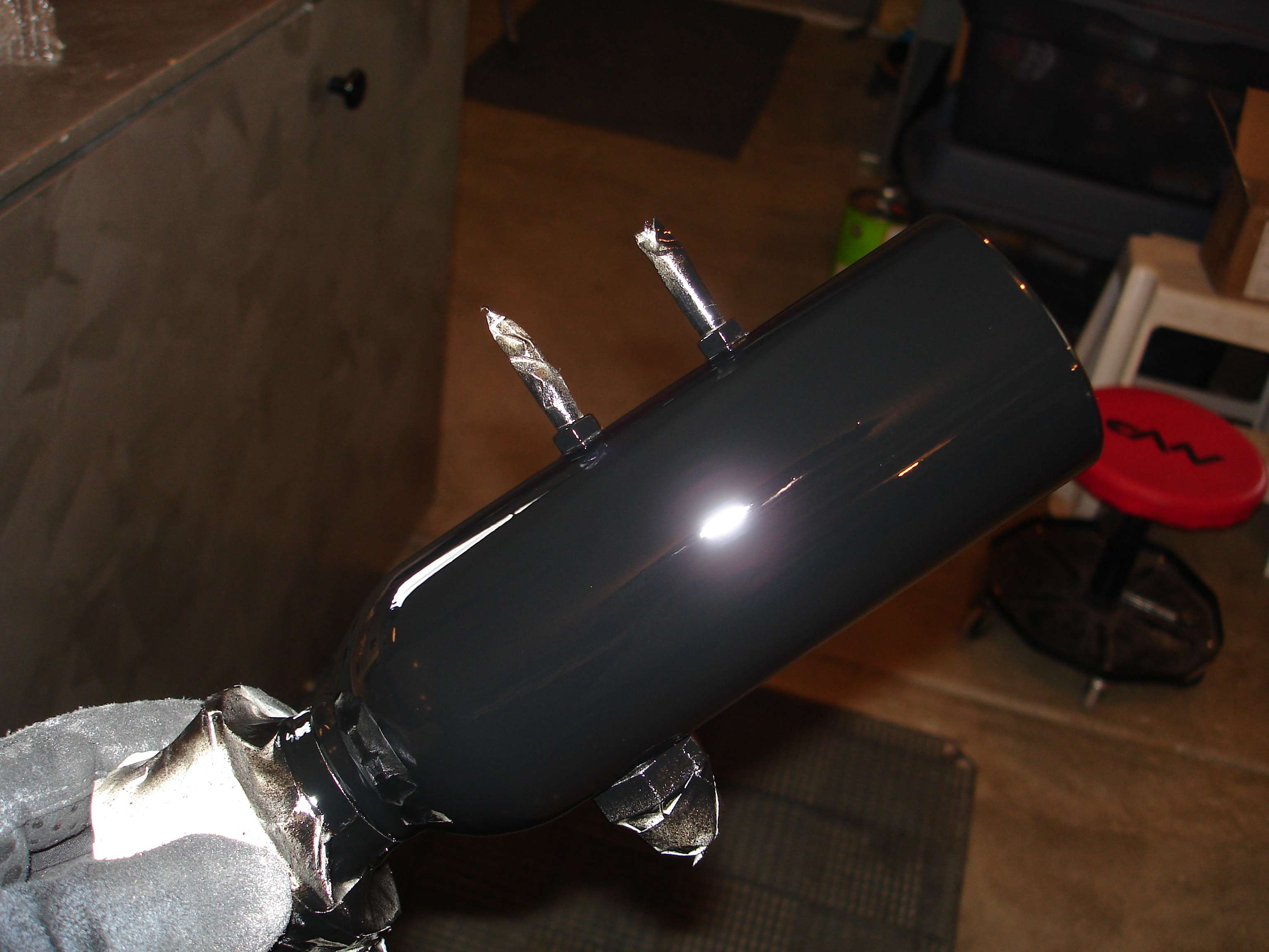
I was going to have my Signature oil catch can powdercoated, but I decided to paint it instead. One of the better jobs I've done, the pics don't do it justice! It is SHY-NEEEE!!!
For those that don't know this can is a sealed unit, with a built in check valve, that will allow blowby to enter the can under vacuum only. This is why I went with an AN fitting in place of the stock PCV valve, as this in essence now becomes my PCV valve. This is NOT just a vent can.
Hopefully my parts are in tomorrow, so I can get this head all done and get the engine timed!
...
Registered User
Only had a bit of time to work on it today, my valve shims are STILL not in.
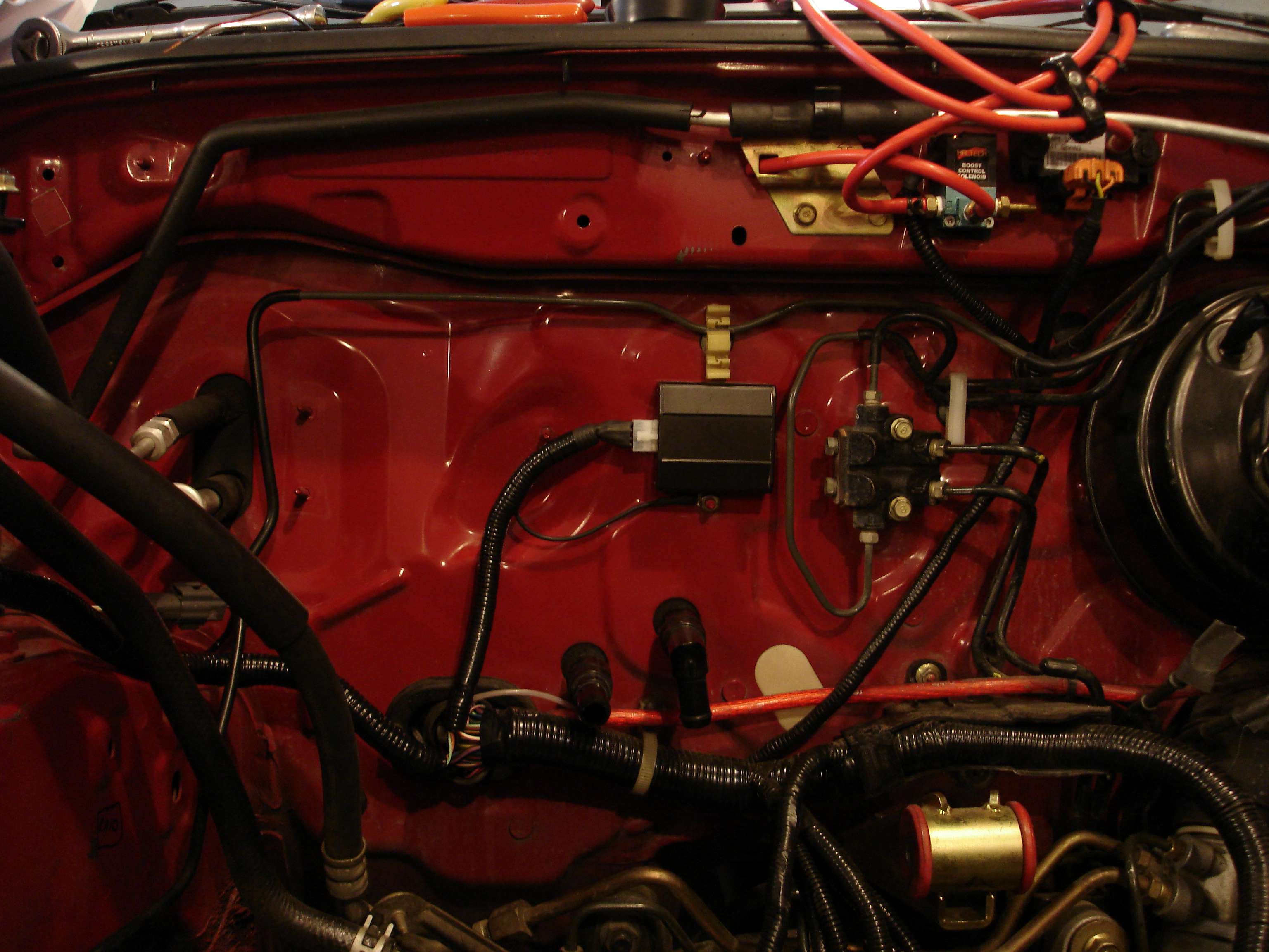
Decided to remount my Haltech RA-10 reluctor adapter on the firewall. The RA-10 takes the analog reluctor signals from my cam position sensor (home) and crank position sensor (trigger) and converts the analog sine wave signal into a much cleaner square wave "digital" signal, that is now output directly to my Haltech E6X standalone as a hall effect signal. The Haltech can use a reluctor signal directly, but having the RA-10 will provide a very clean interference free signal at even extreme RPM's.
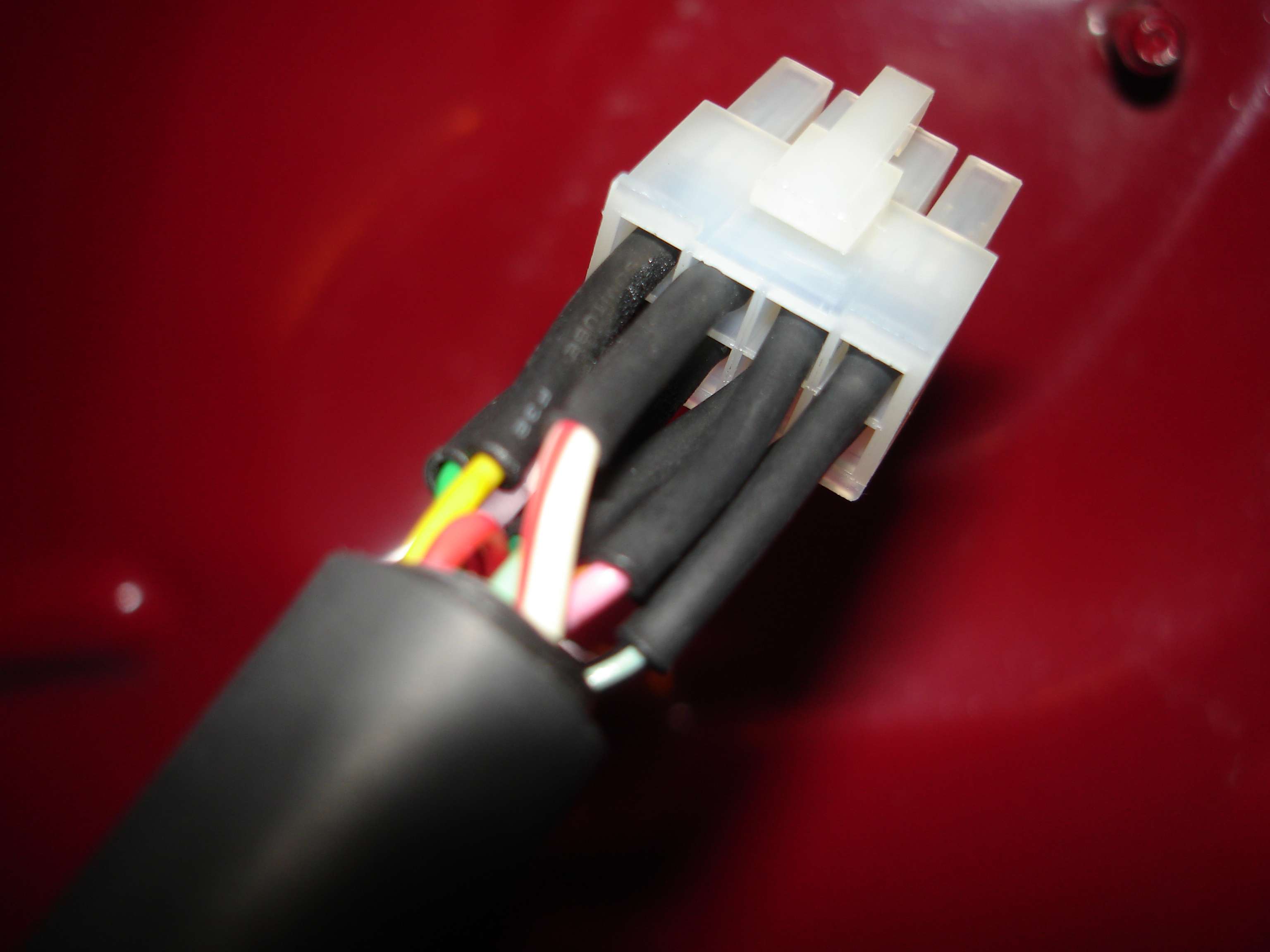
You'll notice I changed it from the ugly silver that Haltech sells it in, to a much nicer matte black. All wires were crimped into new pins, and then heatshrinked individually:
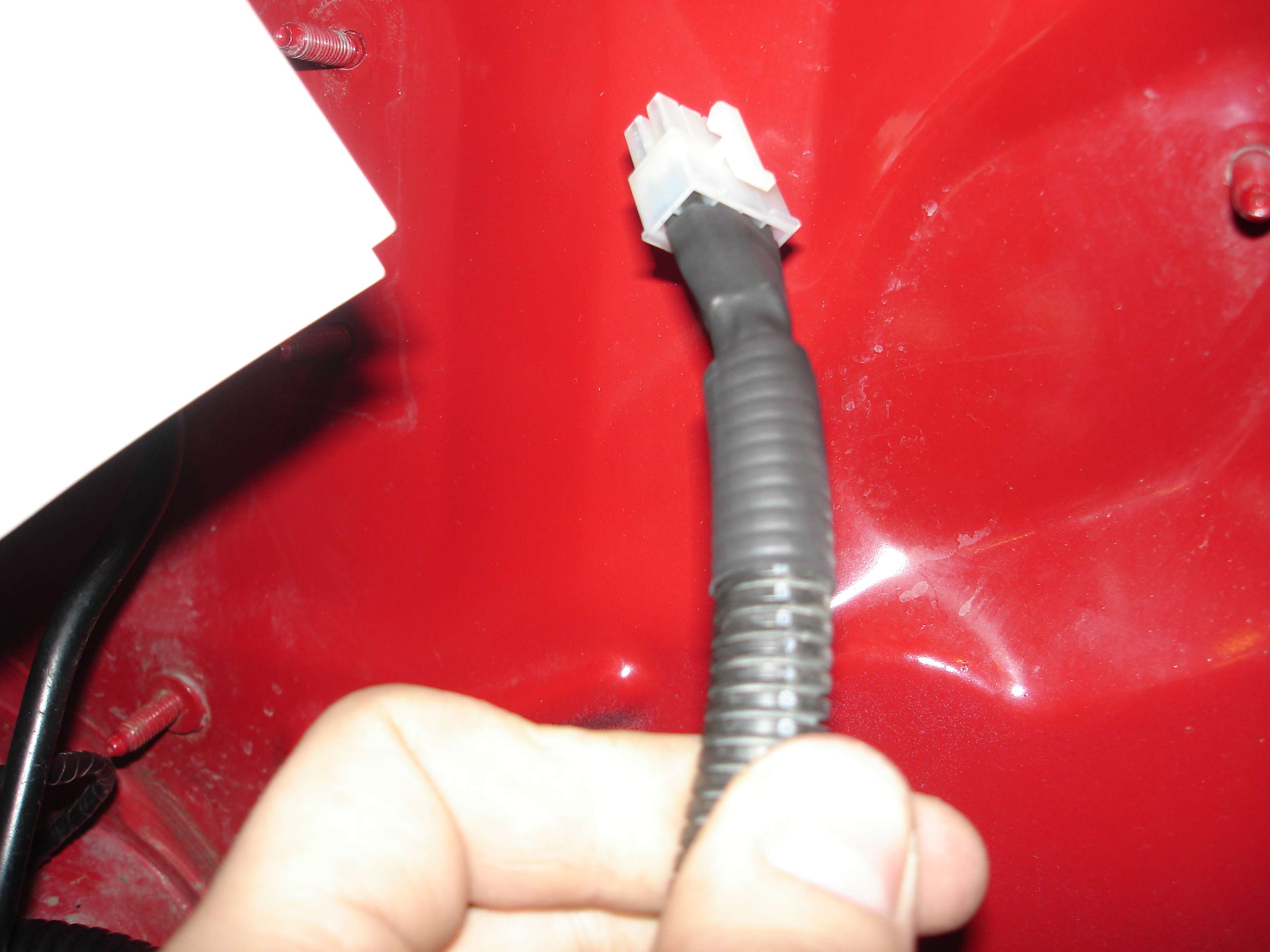
Then the bundle was loomed, and one big piece of heat shrink was used to seal it all off:
Yes, this is probably more work than is ever nessicary, but there is no such thing as "too good" for me. I'm keeping this build top-notch. A ground wire was run to a standoff directly below the unit. I made sure to strip the paint to ensure a good connection. The ground wire was heatshrinked as well.
The finished product. Can't hardly notice it? Good. That's the point.
...
Registered User
Reserved
Last edited by Maxx Mazda; 05-20-2011 at 09:45 PM.
...
Registered User
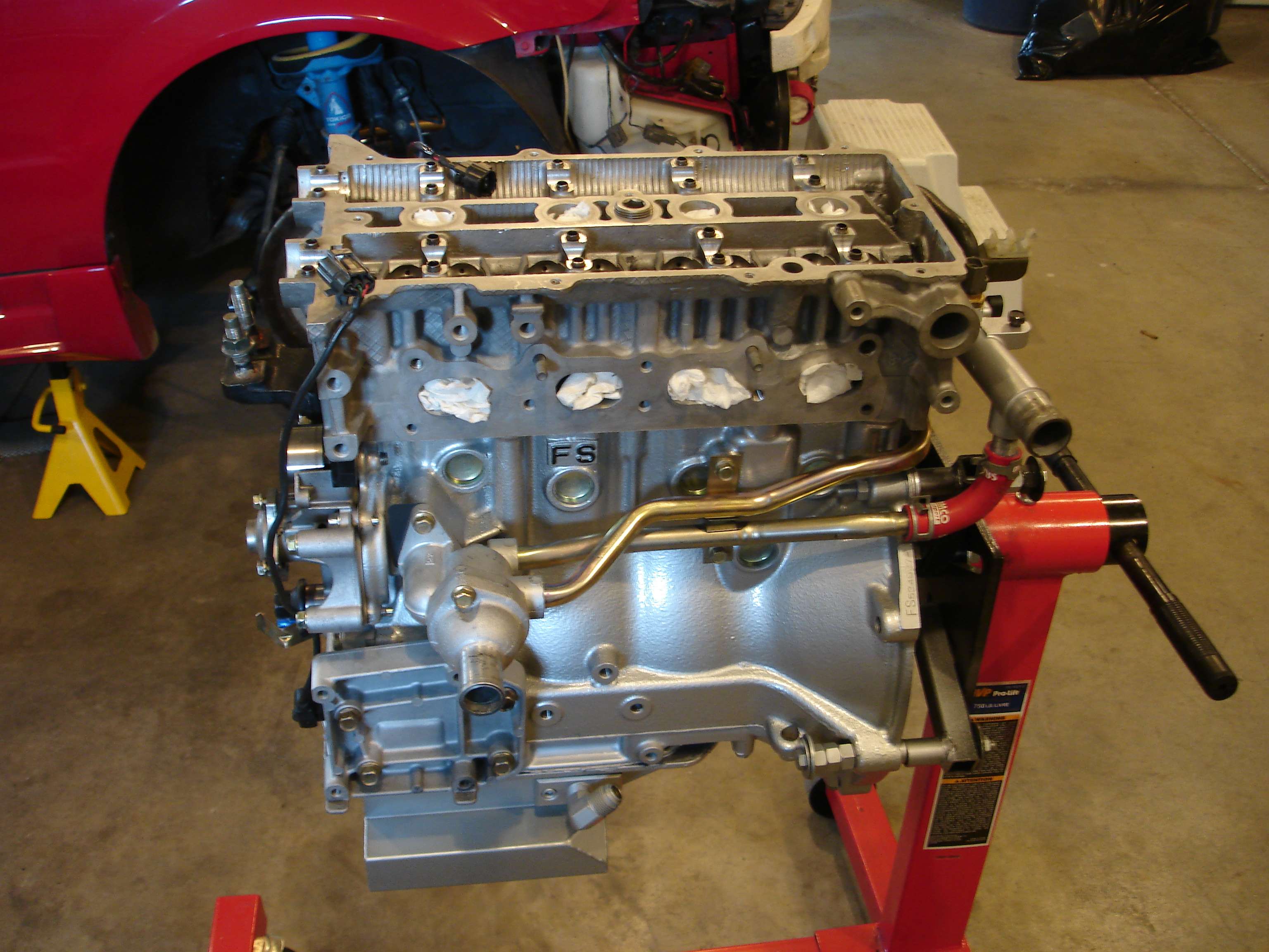
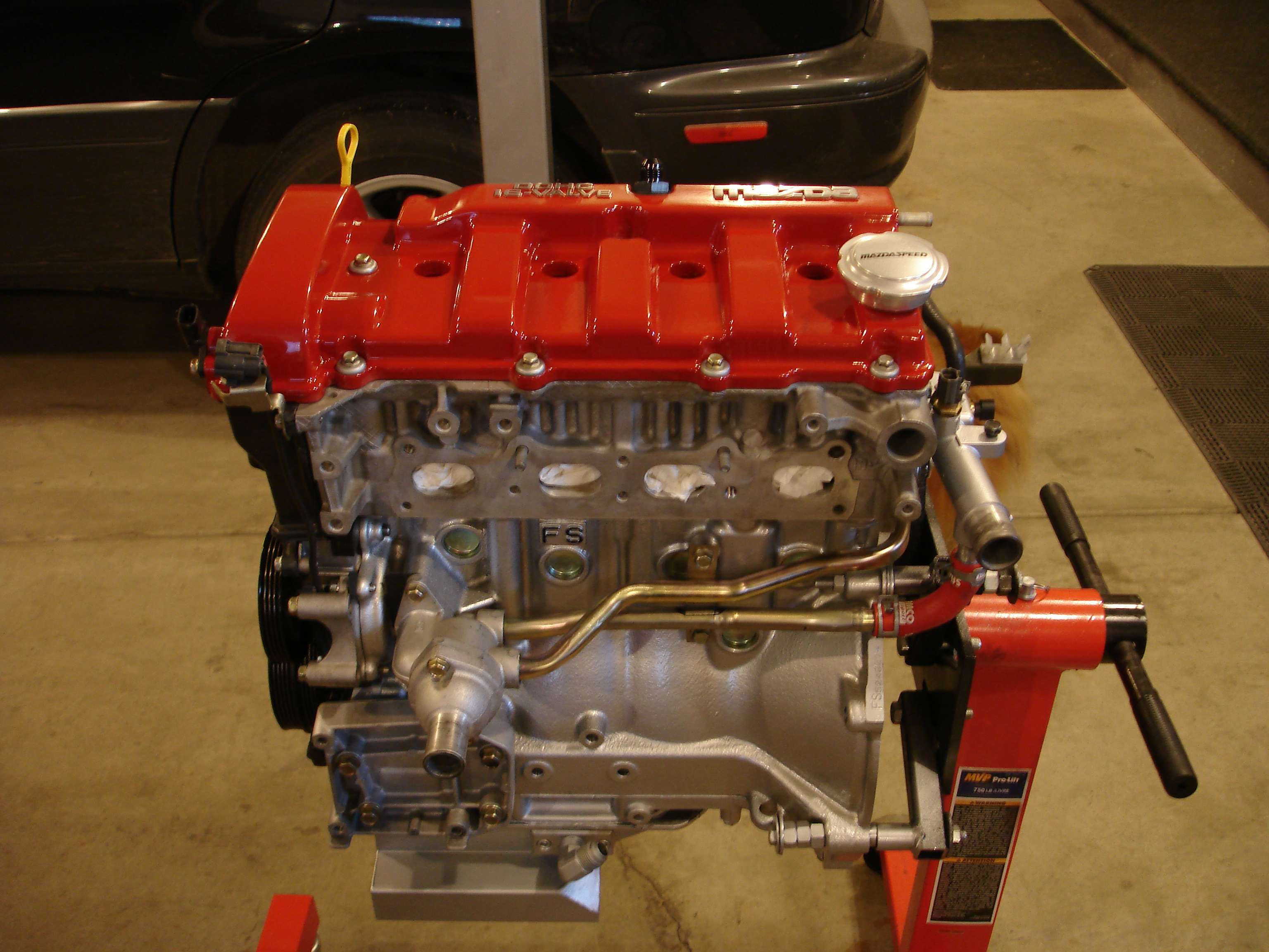
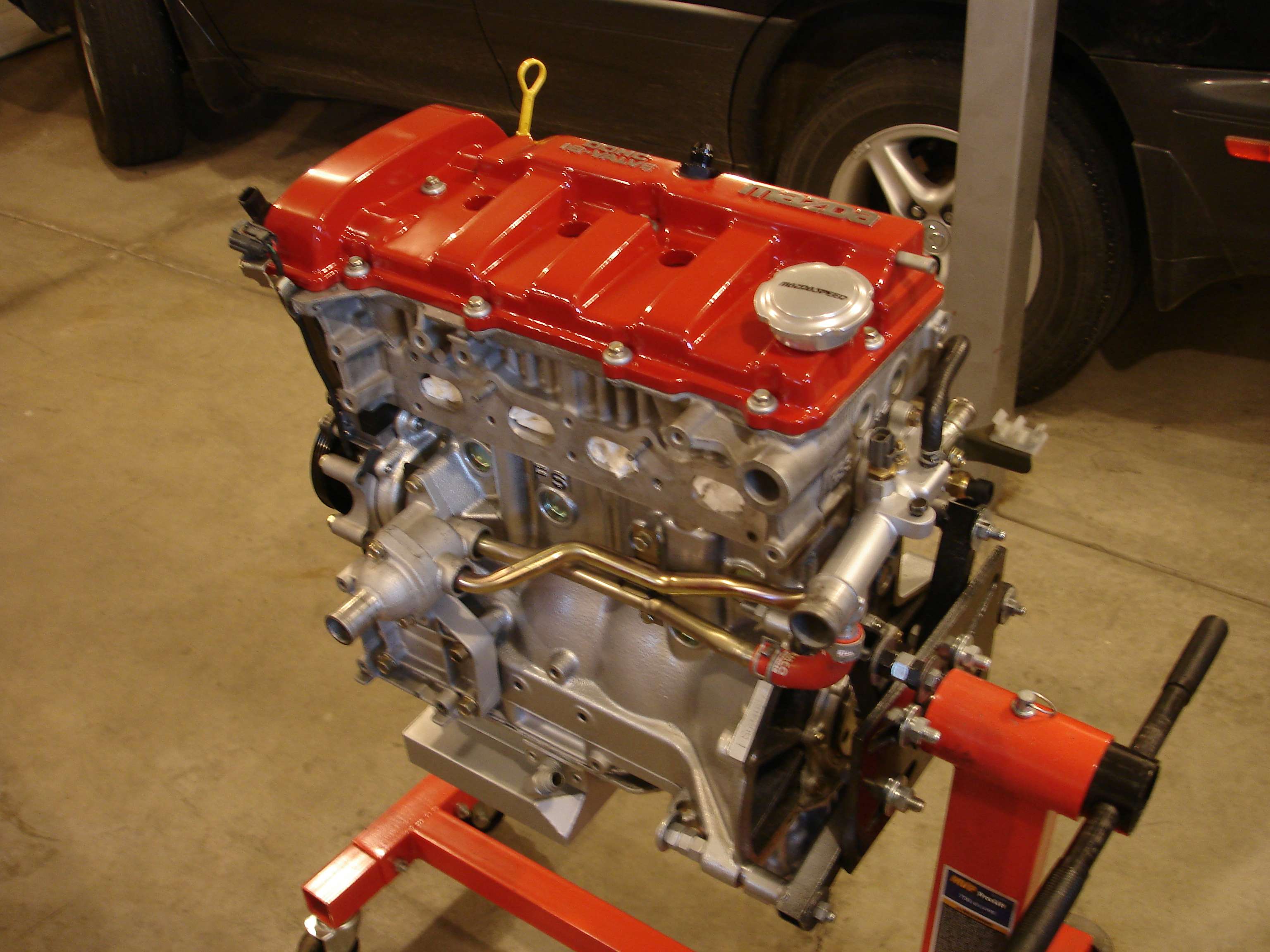
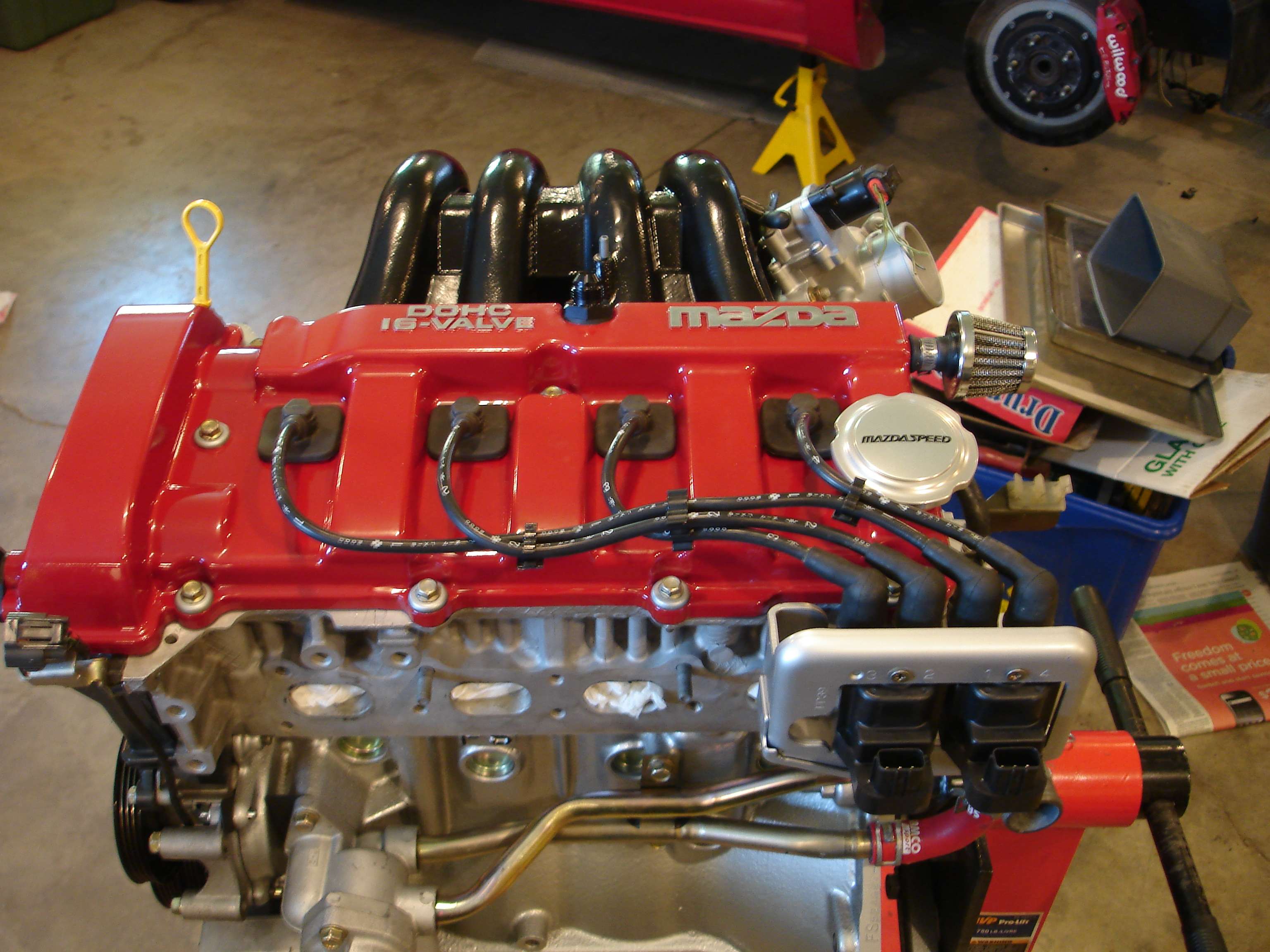
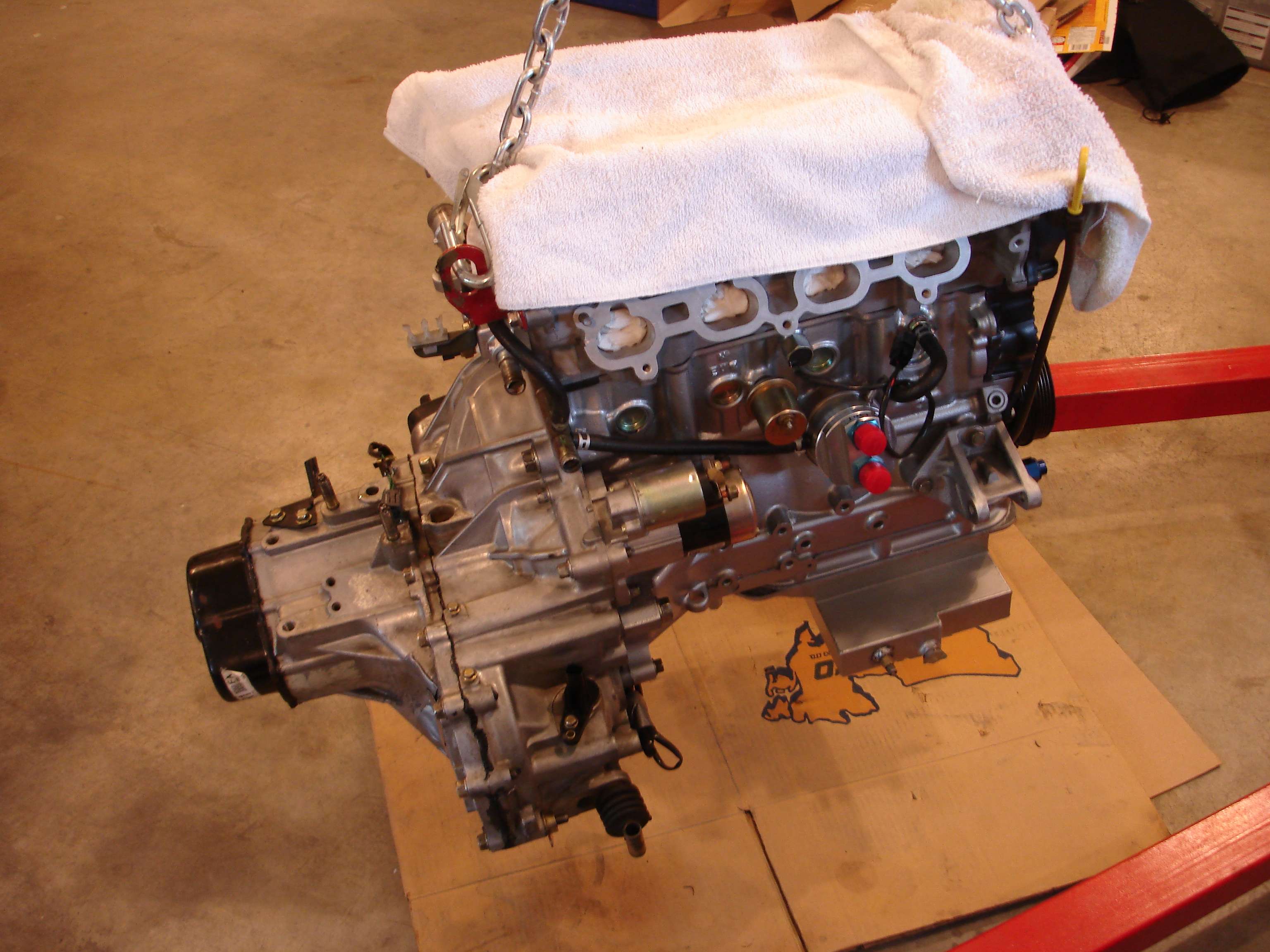
Well, the engine is DONE! Blueprinted and assembled, ready to drop in the car.
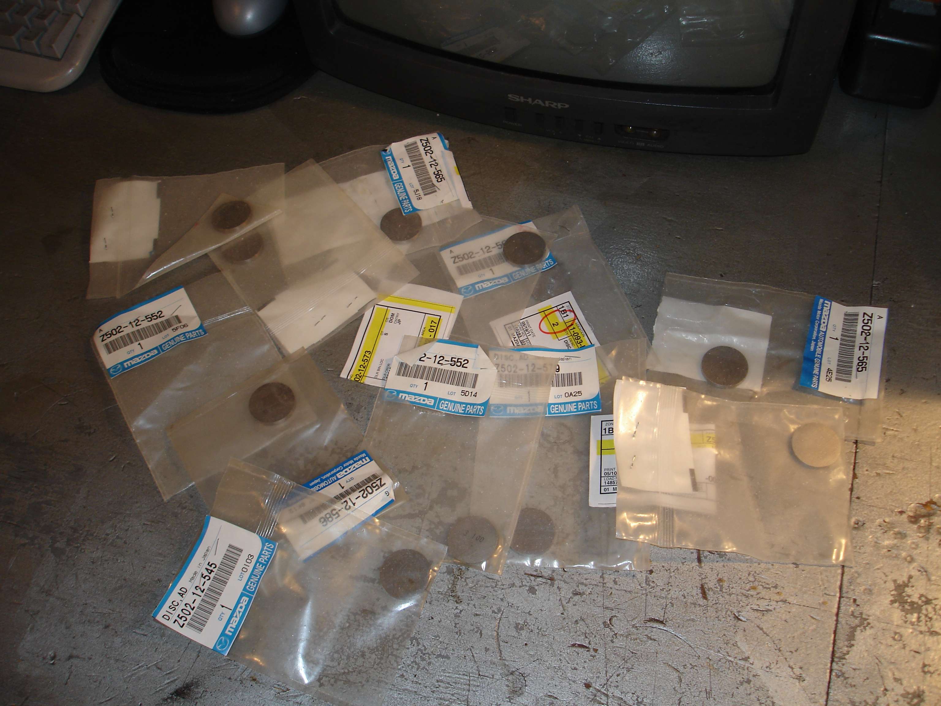
Recieved my last valve shims so I could finish it off. Needed a total of 14 shims, at close to $9 each, you do the math...
New shims are nice because the measurement hasn't worn off yet.
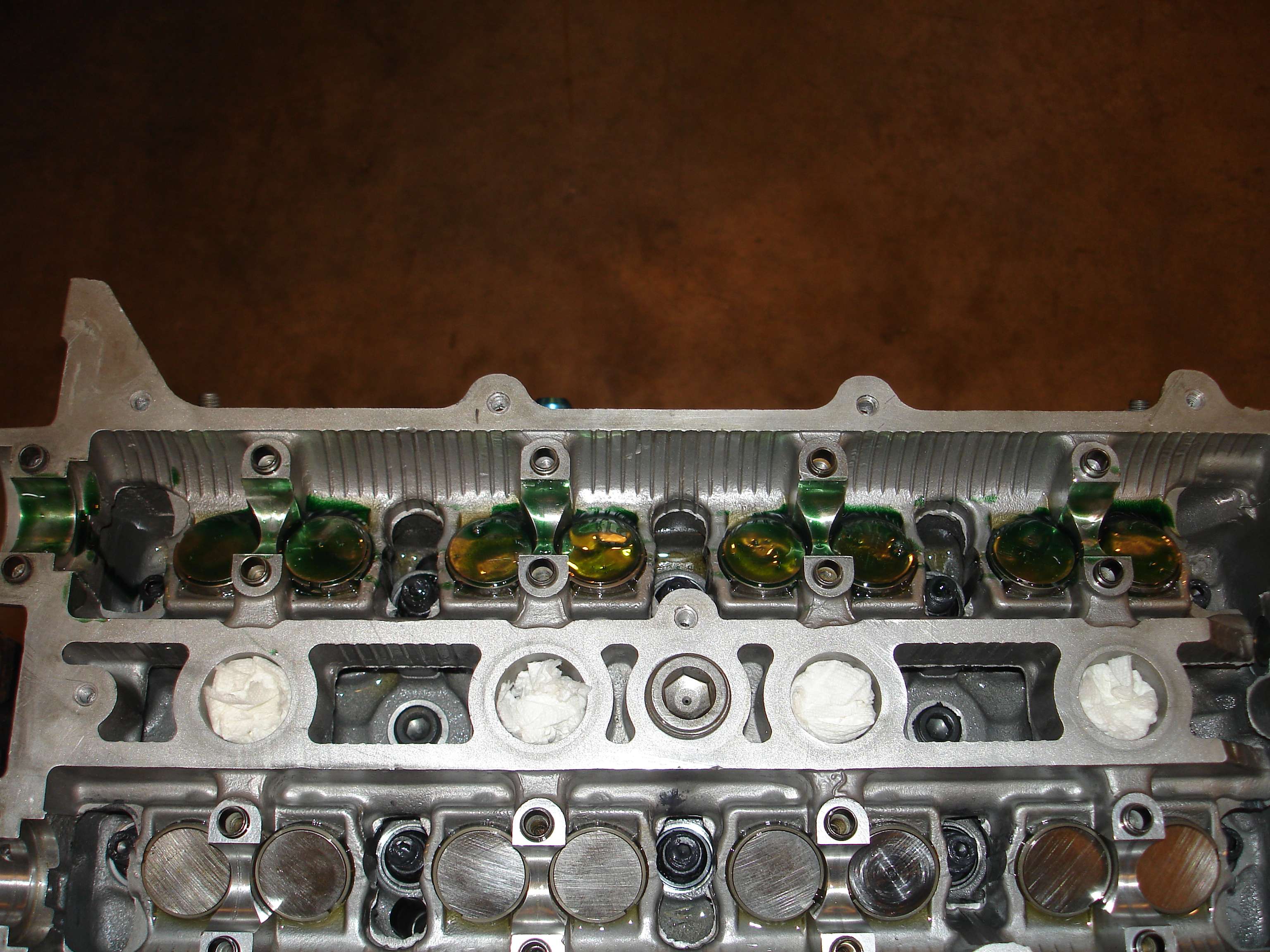
New shims installed in the correct locations. This is where my previous meticulous note taking comes in handy in speeding up the re-assembly. Everything was coated liberally with assembly lube.
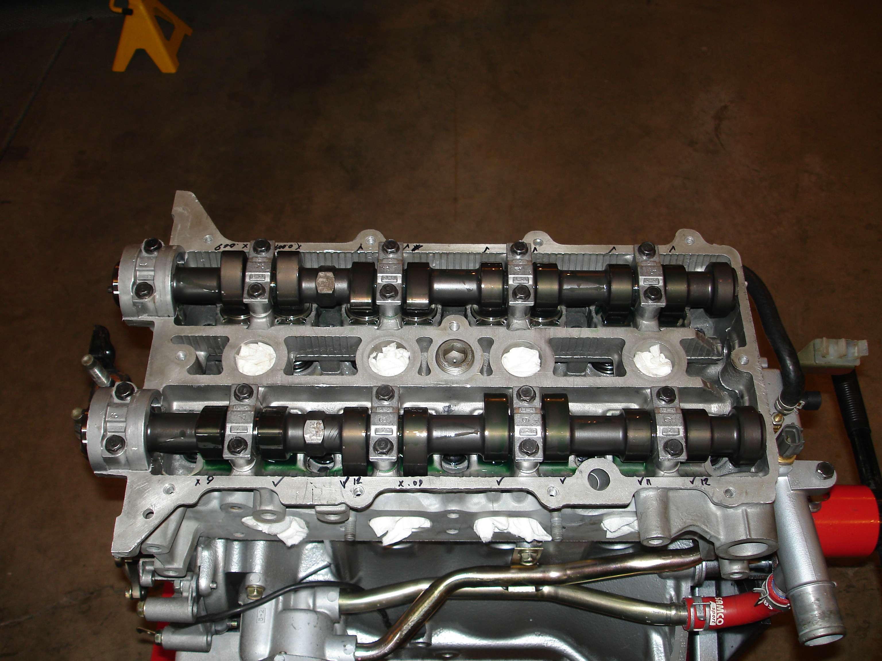
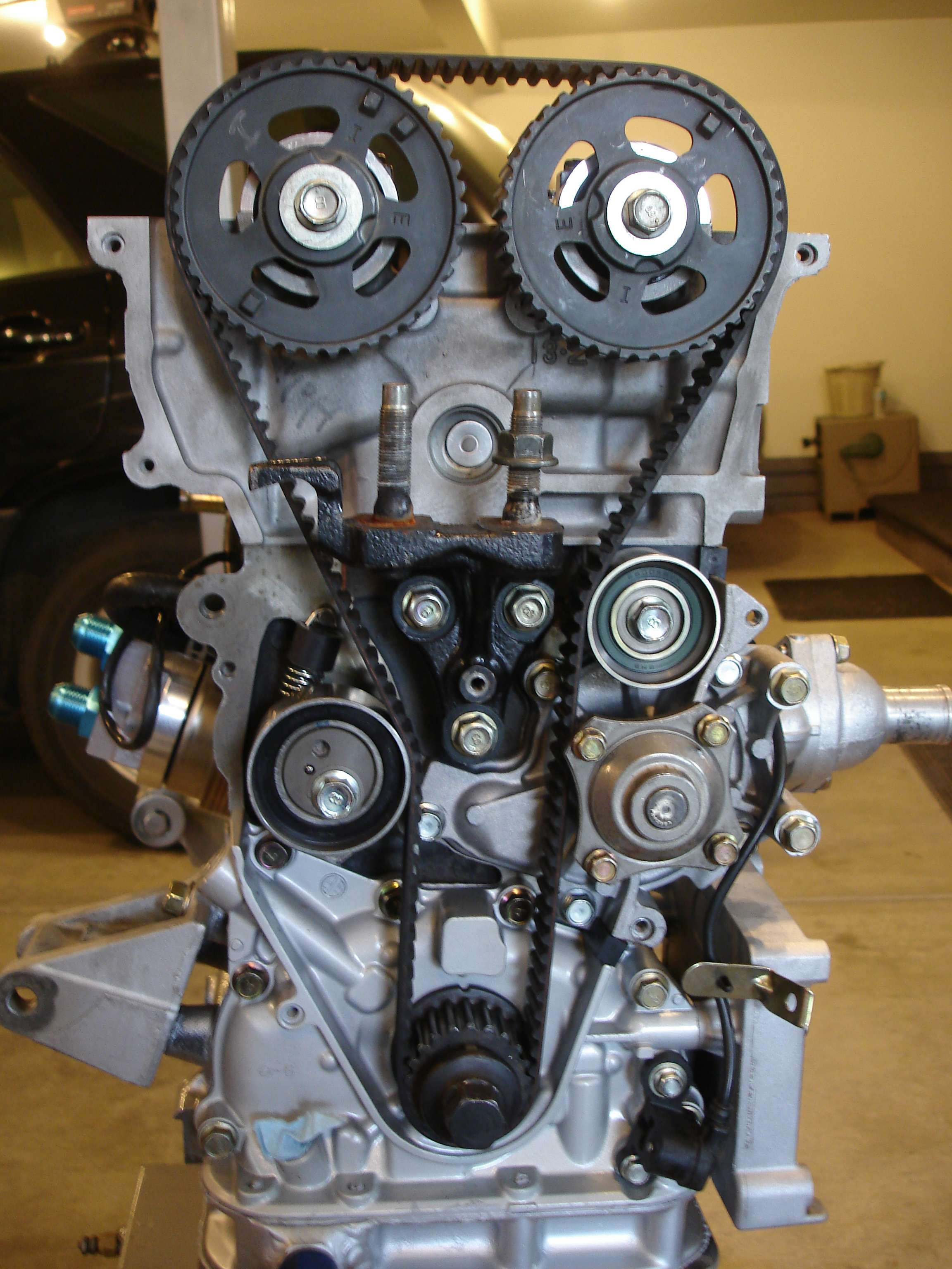
Cams in, and caps torqued down, we can rotate the cams to the correct position and double check our clearances again. Remember, we're looking for 0.009"-0.0012", aiming for the looser side of spec. All shims checked out within spec!
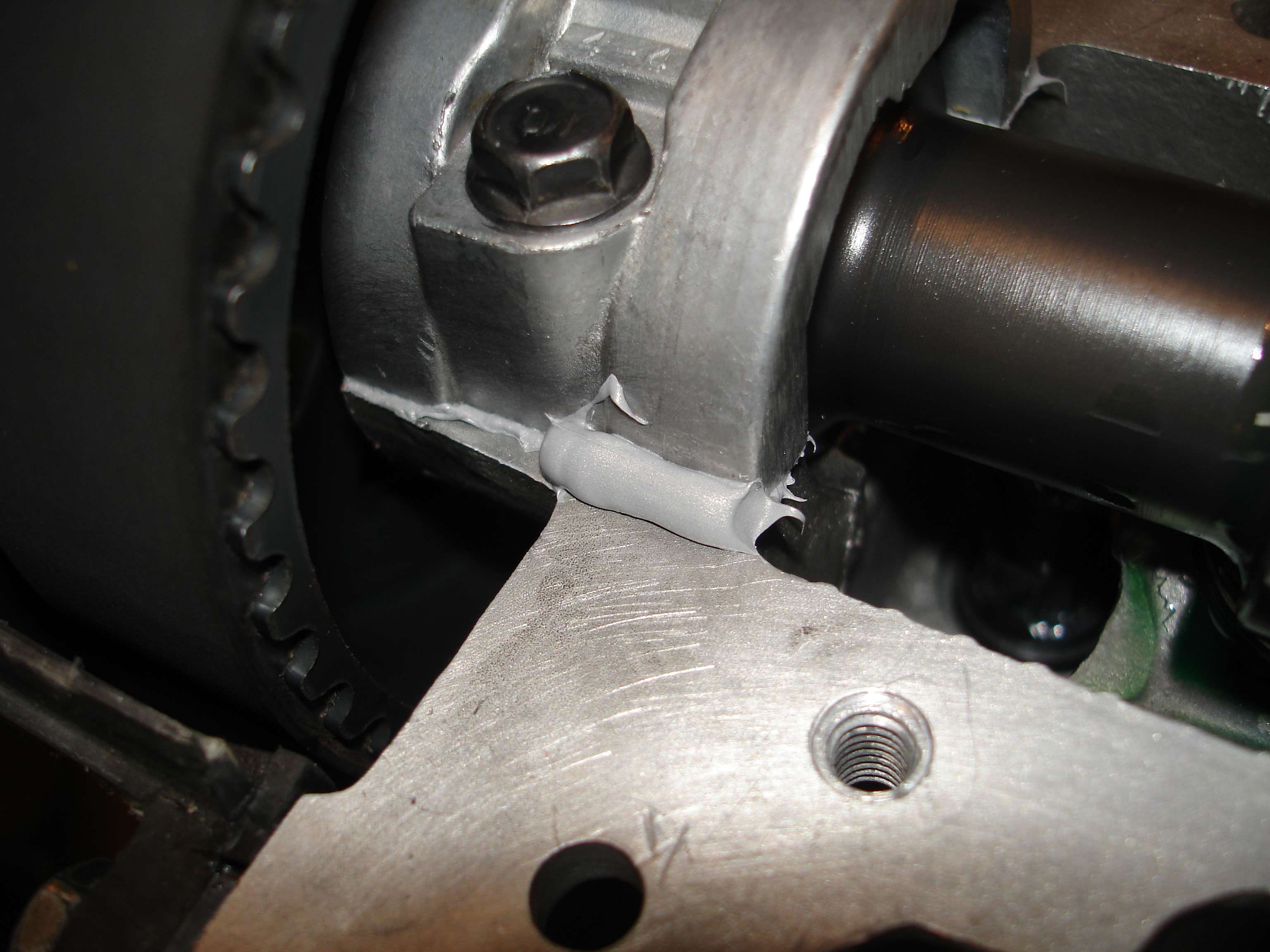
Completed head. Remember to use silicone sealant on the end caps.
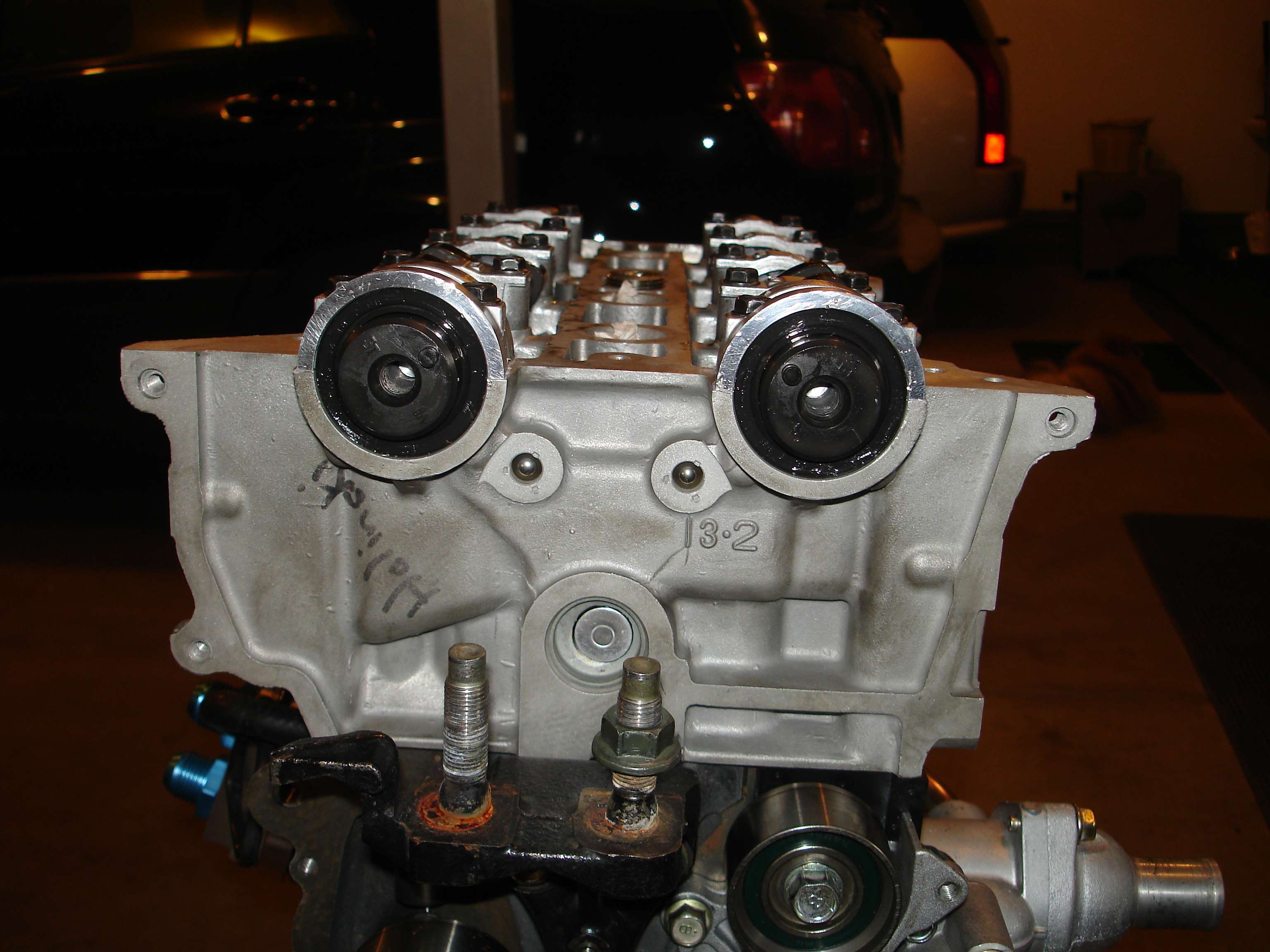
Fresh cam seals were pressed in, and the engine timed. The 626 exhaust cam gear is shown, having only one home pickup, vs. 3 on the stock intake cam gear:
NOTE: The second picture shows the engine timed incorrectly. (Obviously the timing was rectified after taking this pic.)
Don't forget the silicone before installing the valve cover!
And finally...
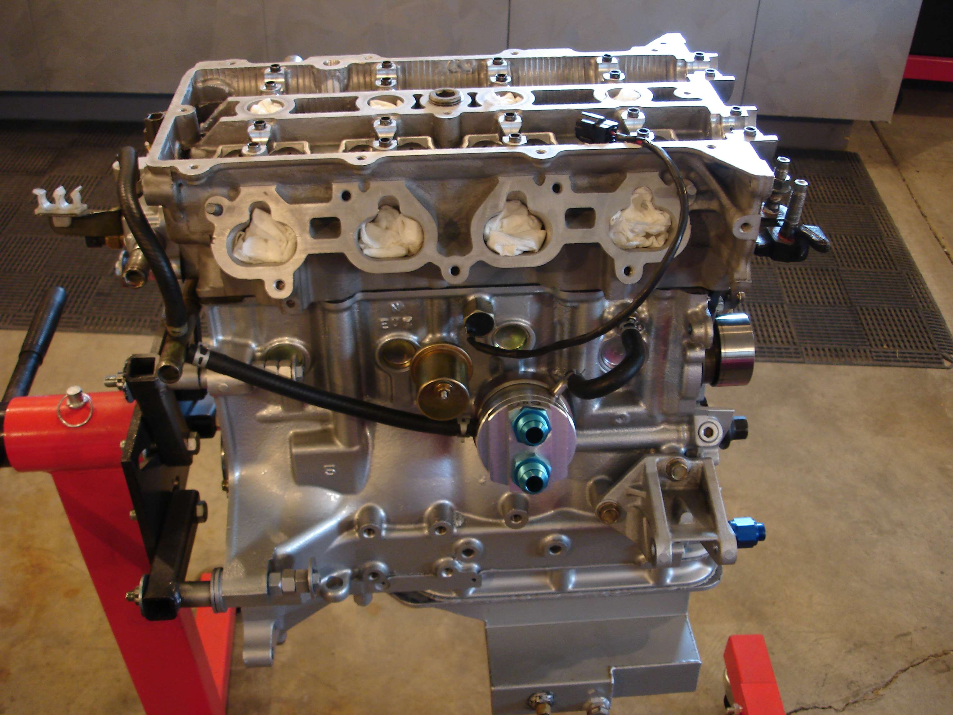
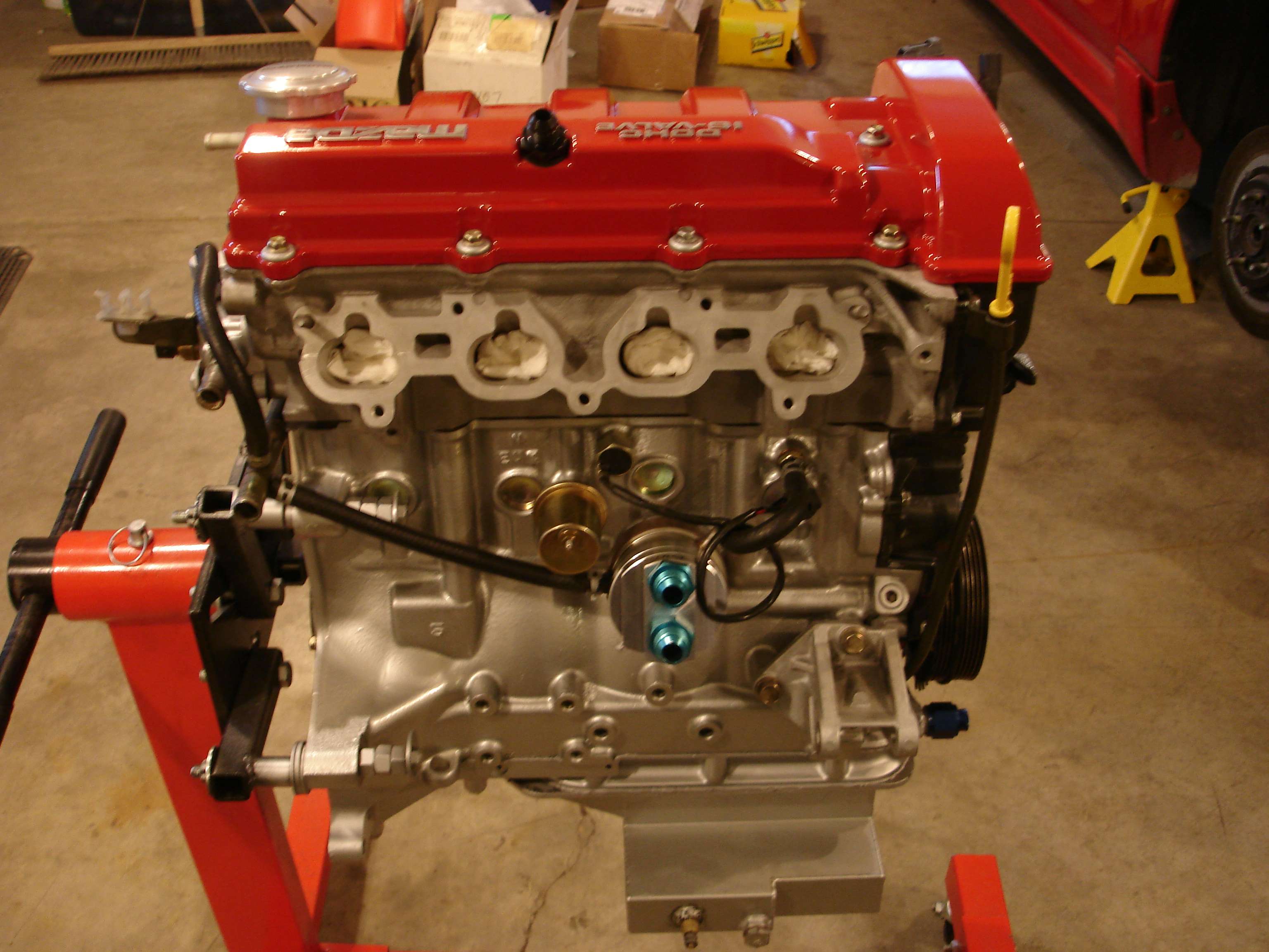
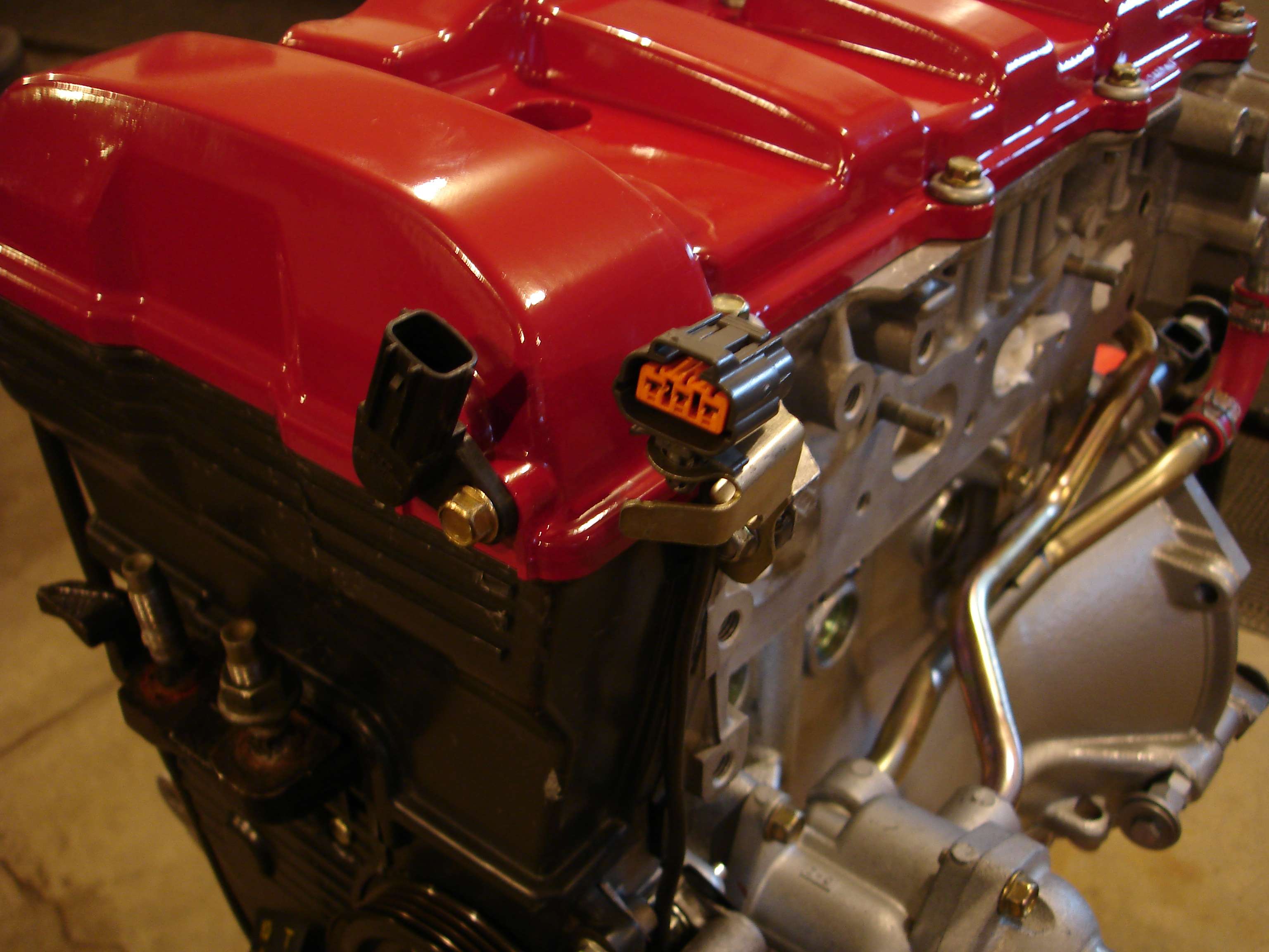
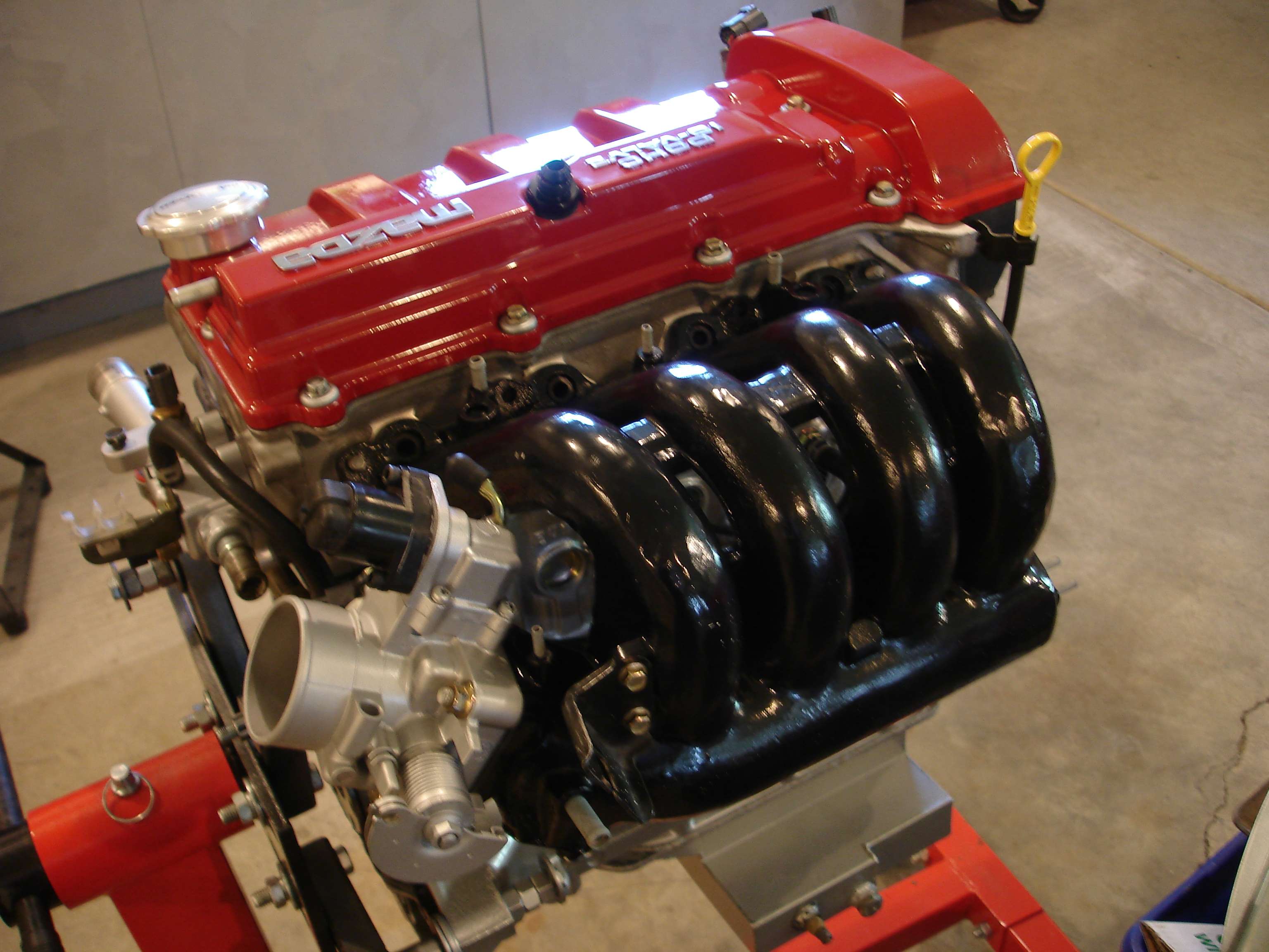
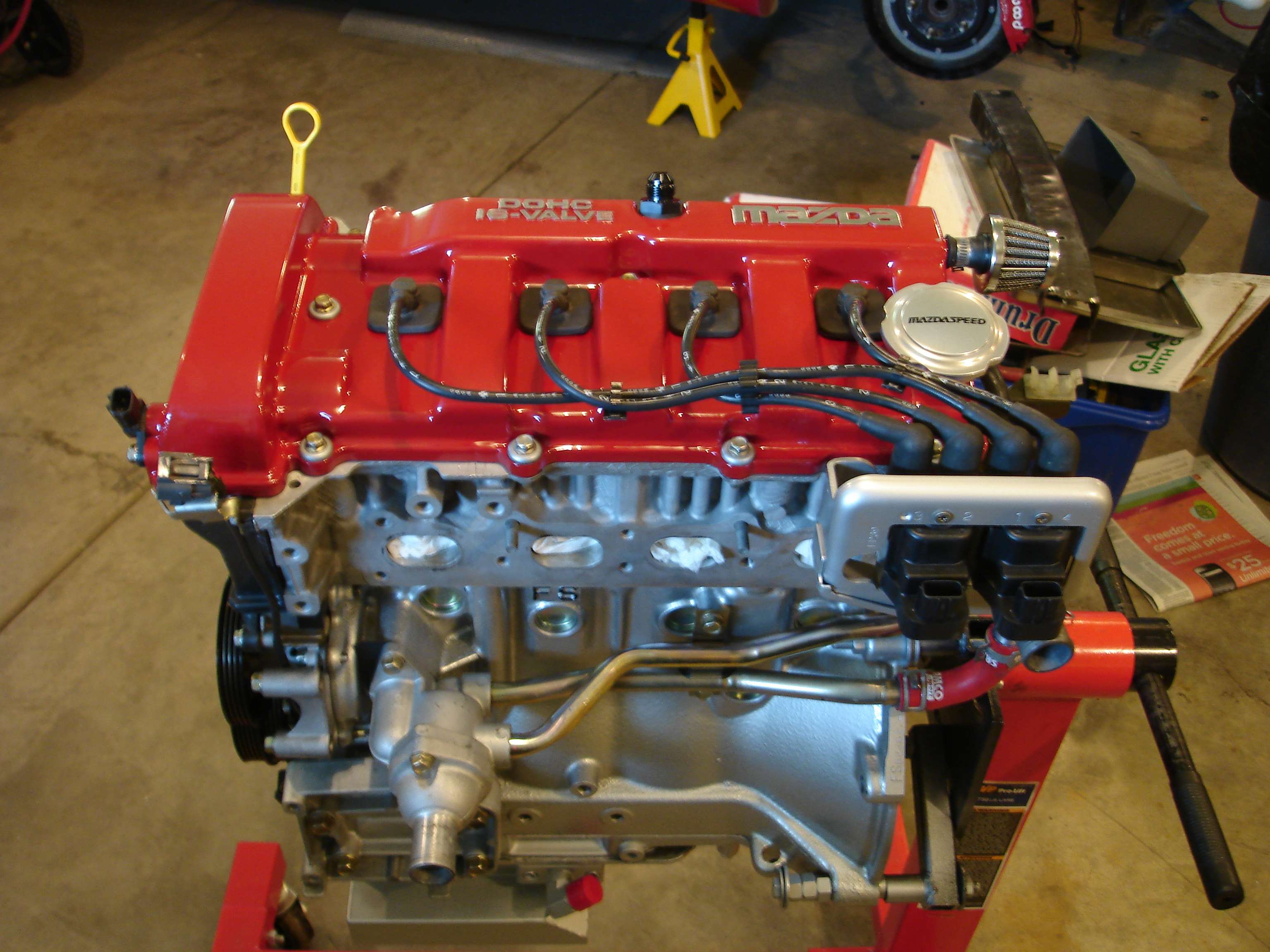
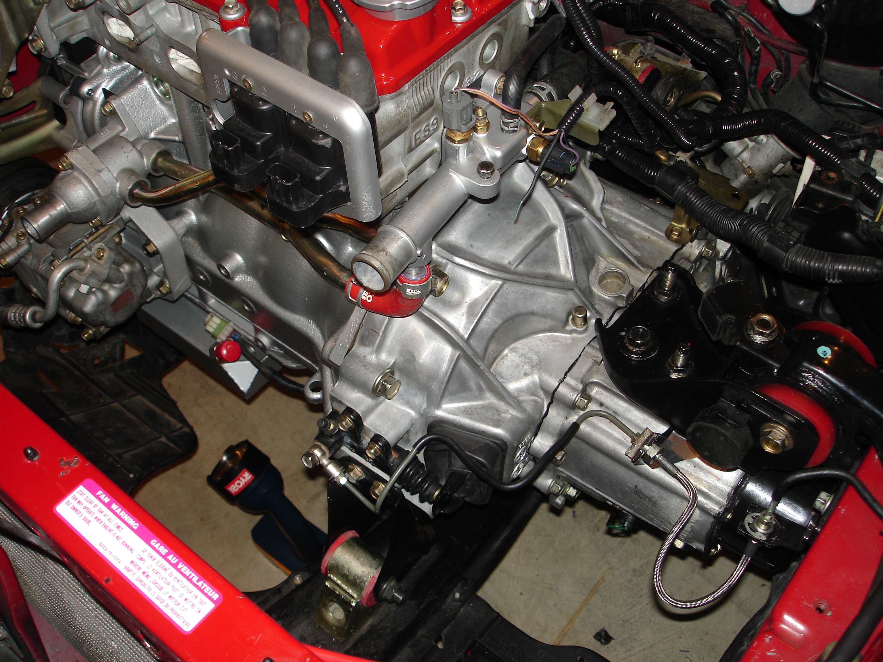
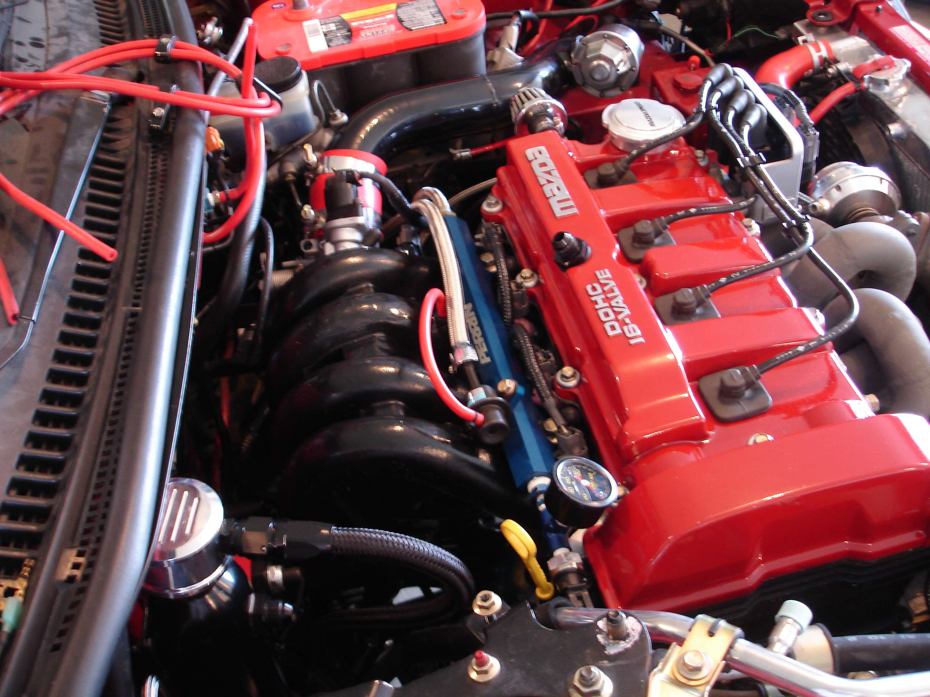
The Completed Engine:
Both cam and crank position sensors are routed to the same area, so that my new engine bay harness will be very discreet.
That's all for now, have a good long weekend everybody!
...
Registered User
So, in looking for a solution for idle control, I was thinking of going with the Haltech stepper motor. I used to have the Haltech control the stock BAC idle solenoid, but I needed that output for another use, so I decided to go with the stepper.
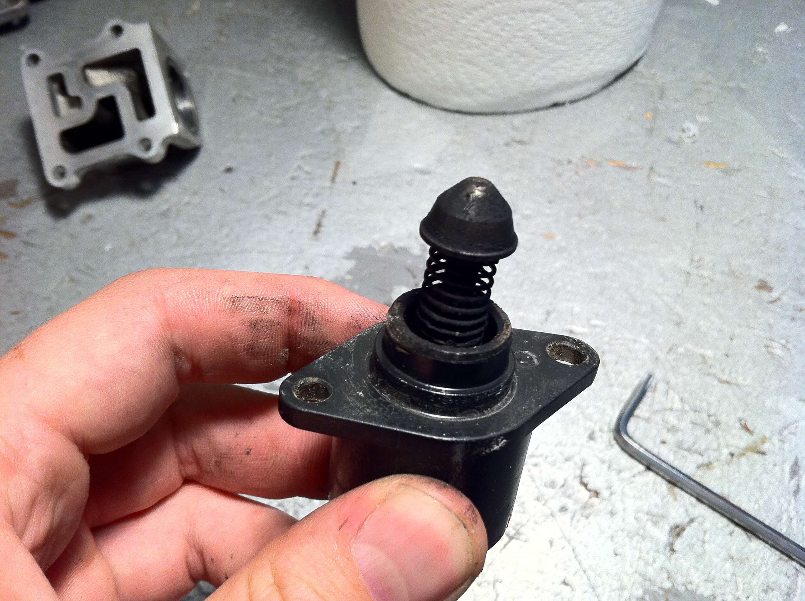
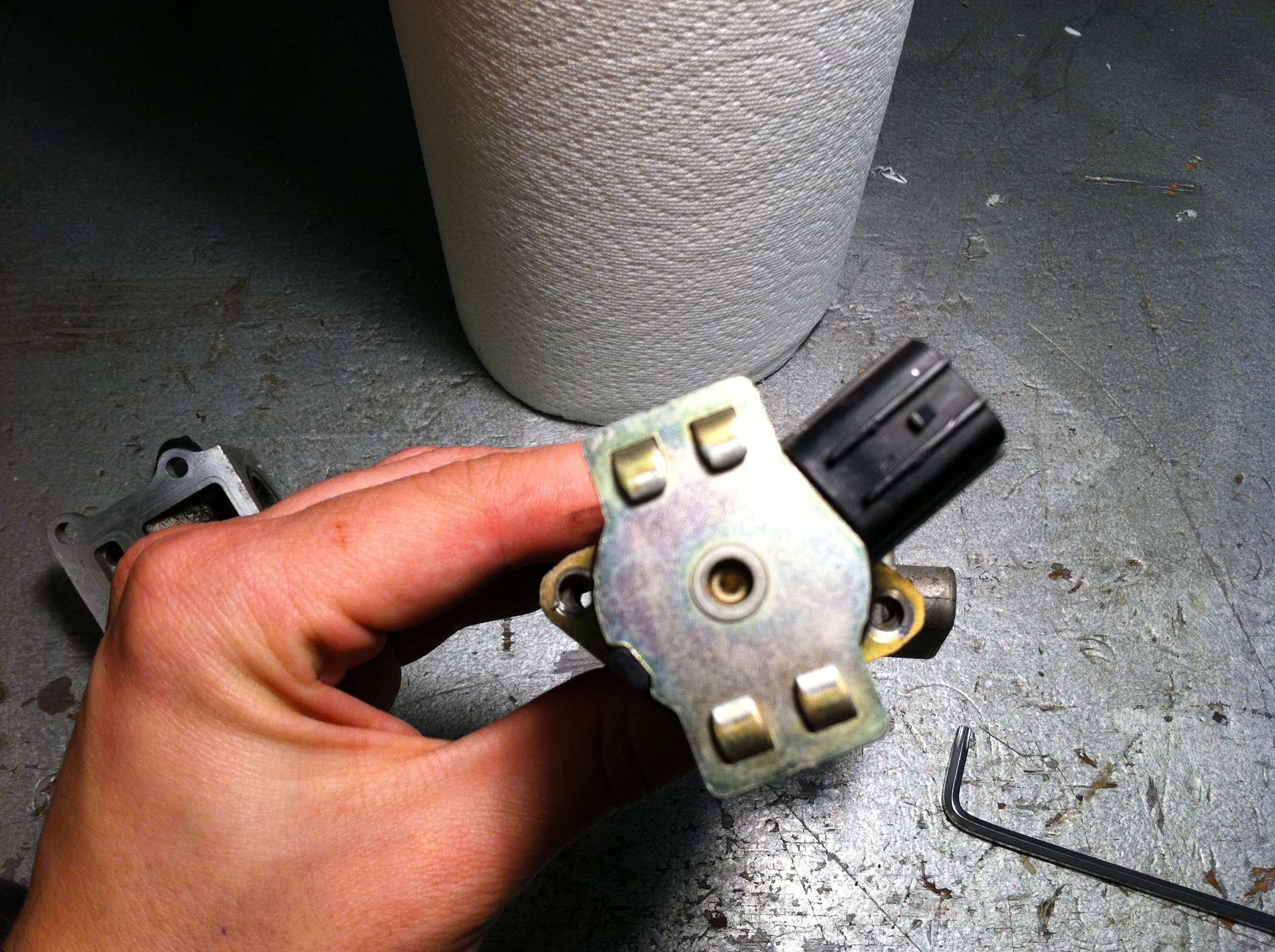
I don't like how the Haltech is a remote mounted unit. Kinda hokey in my opinion, and as such it does not belong on my car. The "haltech" idle solenoid and housing, are in fact just a standard GM screw in type IAC valve and Electromotive billet housing. The GM IAC valve was used on countless GM cars from the mid 80's until 2005. Very popular unit. Robust, cheap, and it works. During this time period, GM used two types of IAC stepper motors. Both the same internally, one was a screw in type:
And the other was the "O-Ring" type:
Again, both are the same internally, but along with mounting types, each one also has a different wire connector, both 4 pin.
Anyway, I wanted a more "stock" looking IAC solution than some cheezy box with hoses and barbs. I wanted to mount the IAC in the stock location, and use the bypasses already present within the throttle body. I could either fab up an adapter to mount the screw in type, or experement with the O-Ring type. I procured an IAC valve of the "O-Ring" type from a '91 Cavalier 2.8L throttle body I had lying around.
Cavalier IAC block and mount:
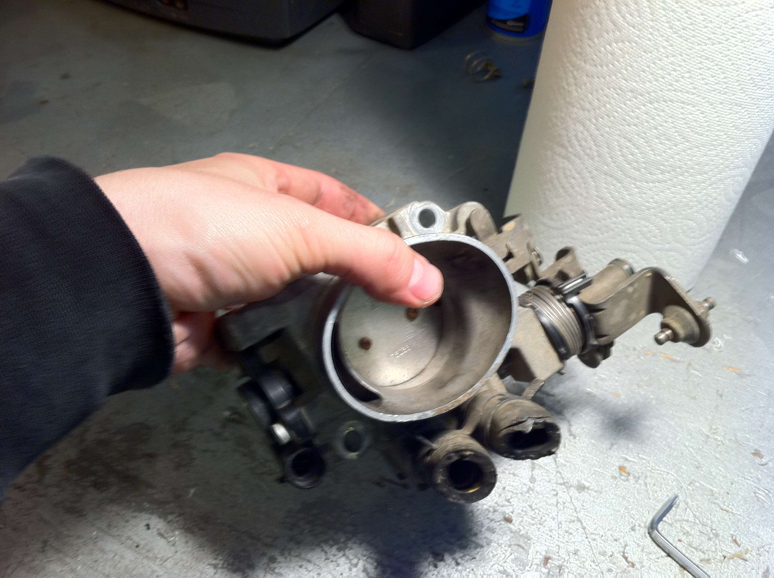
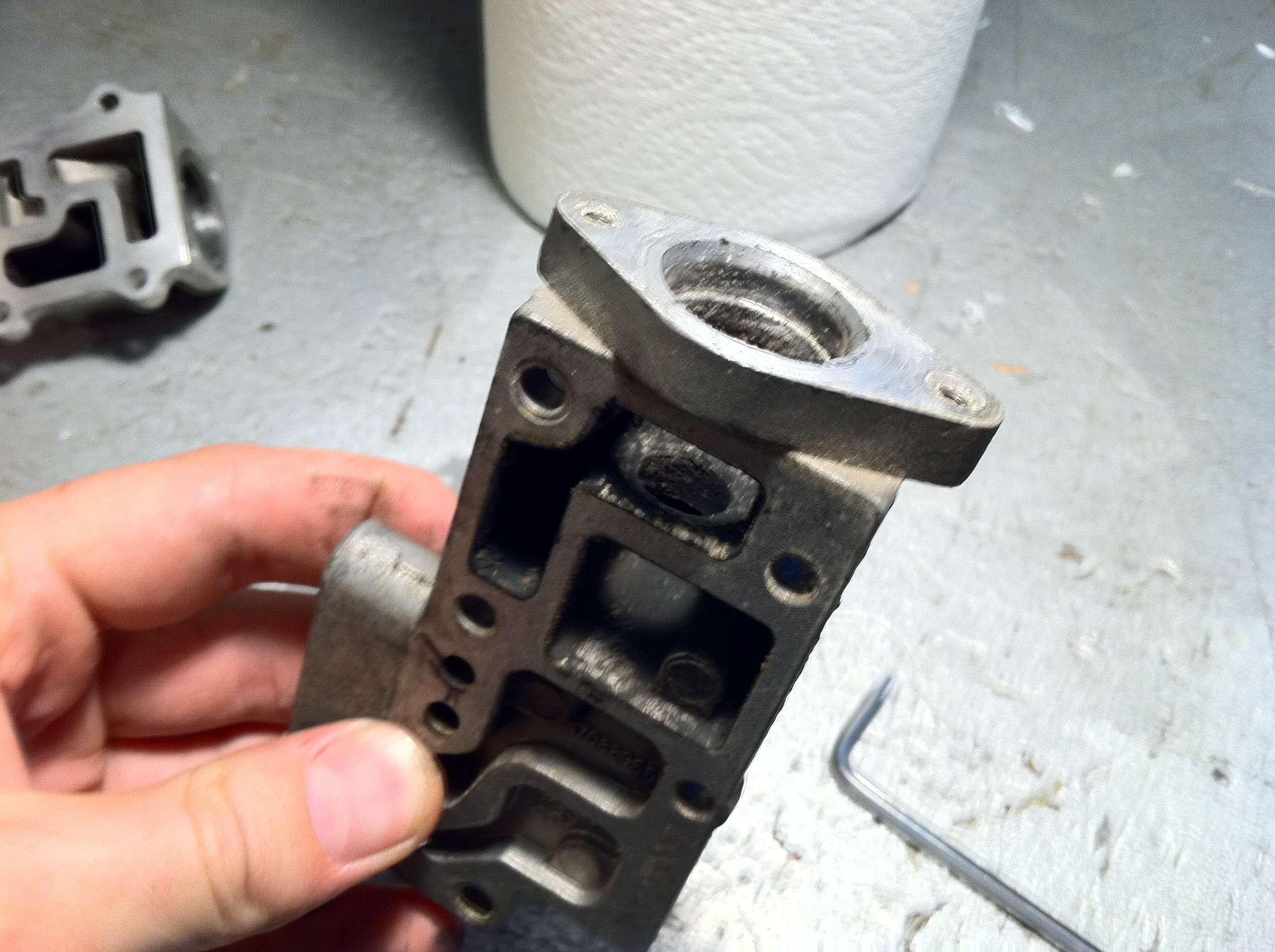
Here is the stock Mazda IAC housing, with the stock solenoid removed. Notice any similarities between the mounting holes for the solenoid, and the mounting points for the stepper motor?
A quick fit of the Mazda BAC valve onto the GM IAC block confirms that the holes line up perfectly.
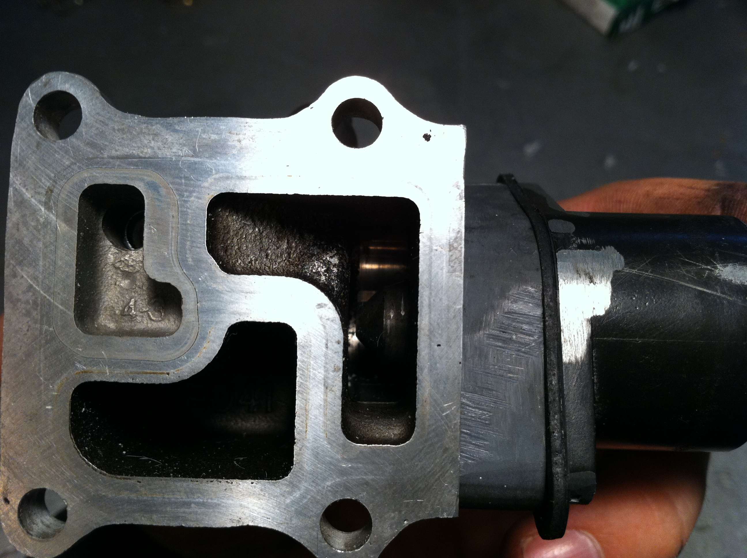
With the stepper motor almost fully extended, we can see that the Mazda housing isn't quite "deep" enough:
So, after some clever fab work, I came up with an interface piece made out of a spare block of PVC I had laying around:
Believe it or not, I came up with another ingenious solution. The gasket for a T3 block style oil feed line fits PERFECTLY as well! It will need a little trimming around the outside.
Now the valve will close fully at around 70% extension, and at fully retracted still leaves plenty of room for bypass air. No doubt I'll have to adjust the available steps and set my throttle base opening position, but other than that, I came up with a great (stock) looking IAC valve, for a grand total of $3. (Had to buy longer screws to mount through the block.) Please note this a VERY rough fit, and will be cleaned up and made to look much better before it's considered finished.
...
Registered User
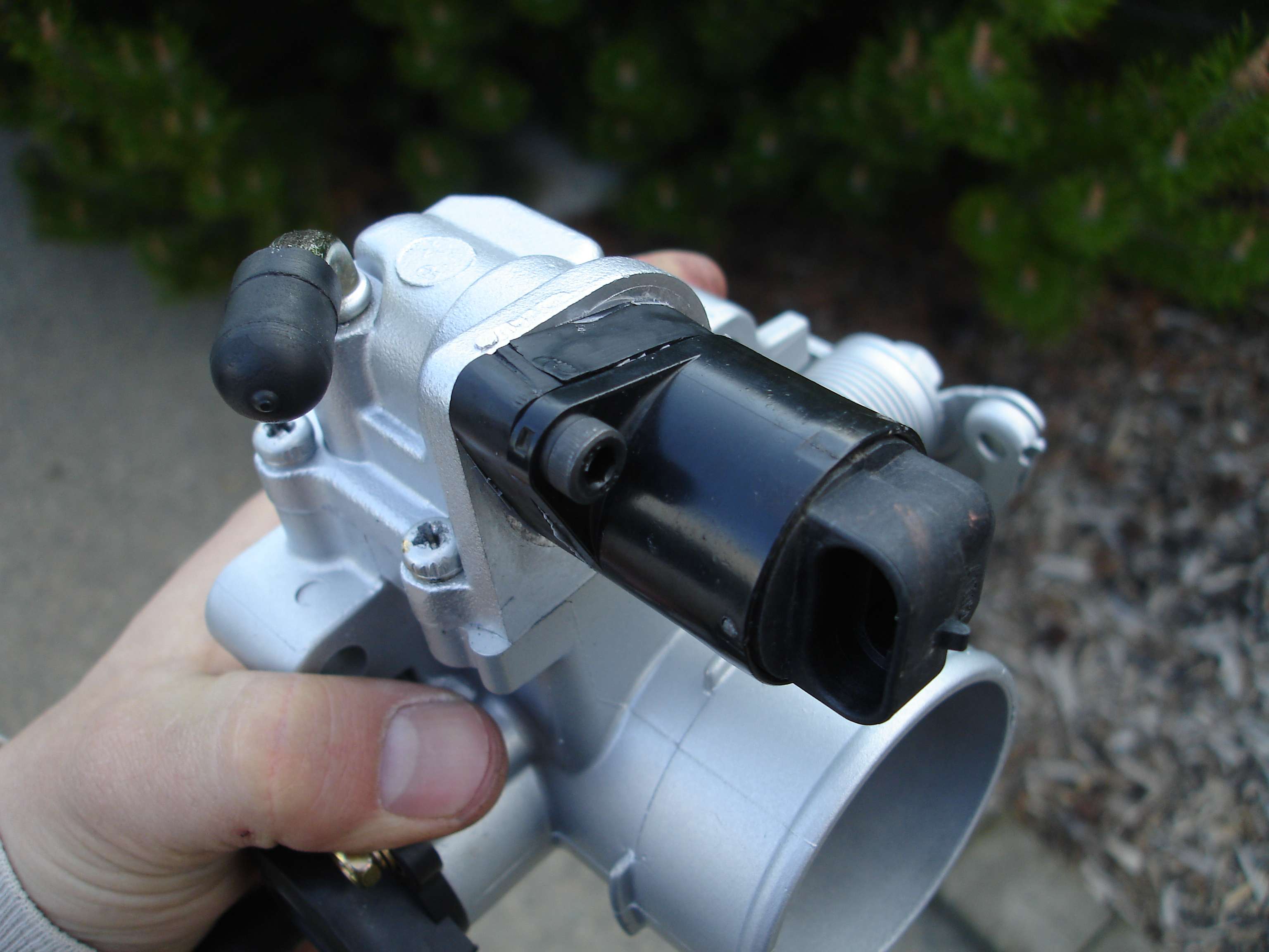
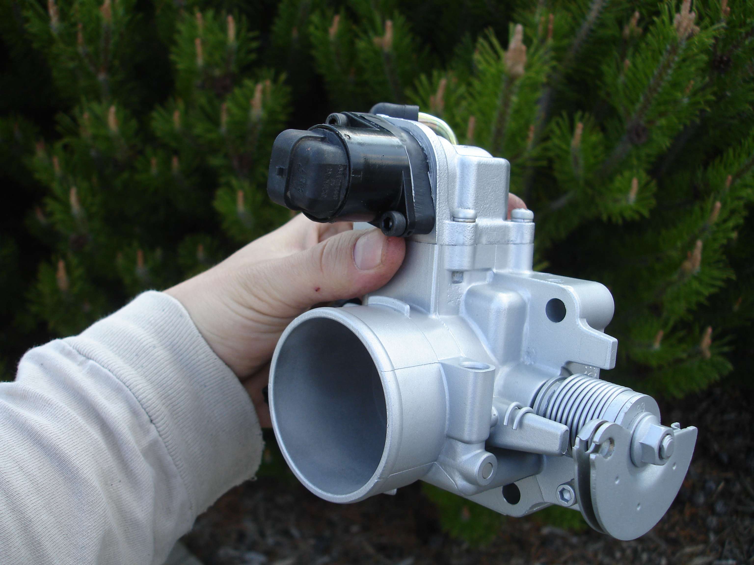
A few shots of the finished throttle body with the GM IAC stepper motor in place. Like I had hoped, it looks stock!
...
Registered User
Got a LOT done today! The deadline is Sunday the 12th to have the car out of the garage for moving day.
Picked up a set of plugs, as always BKR7E's. I gap to 0.040"
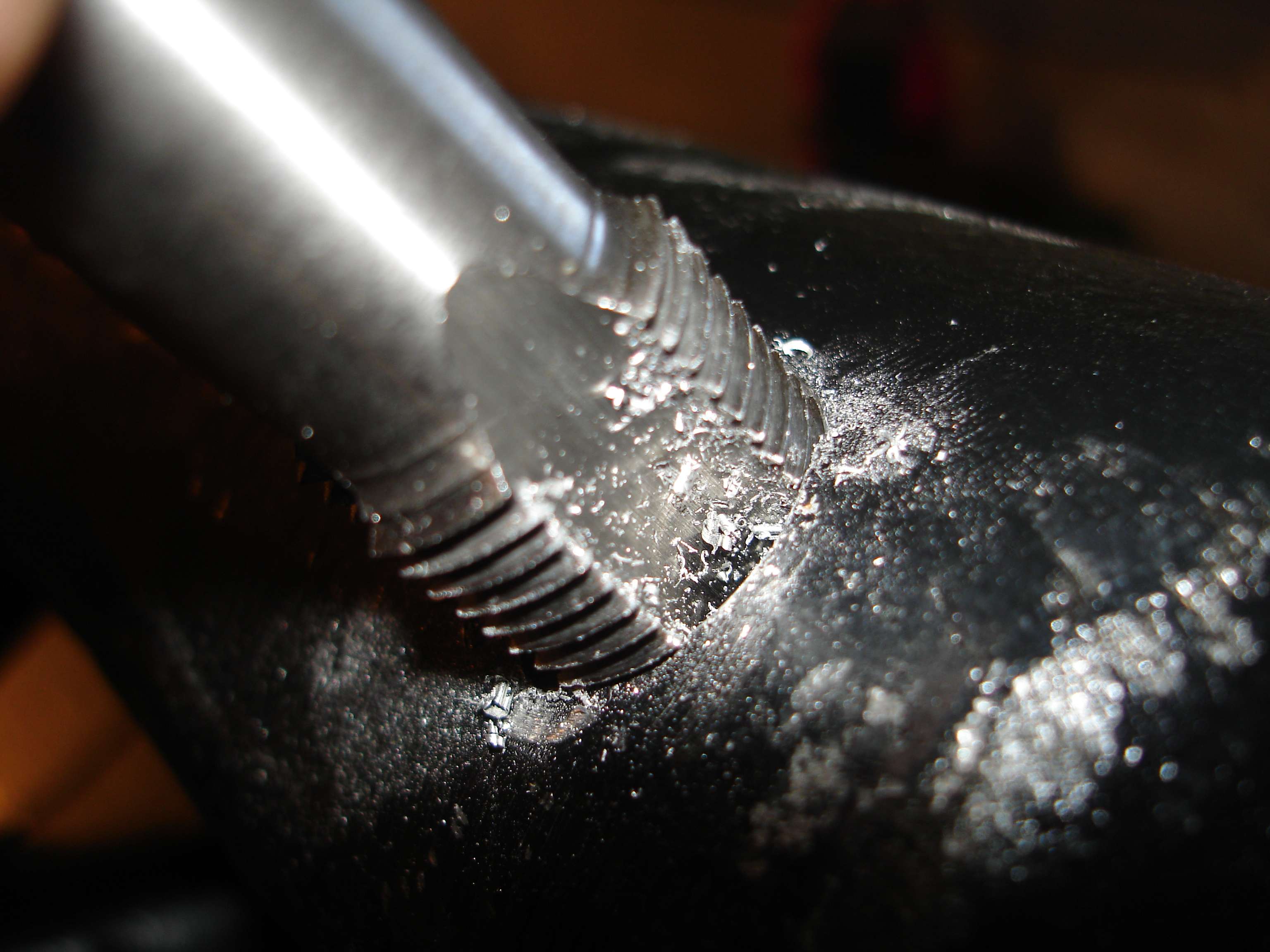
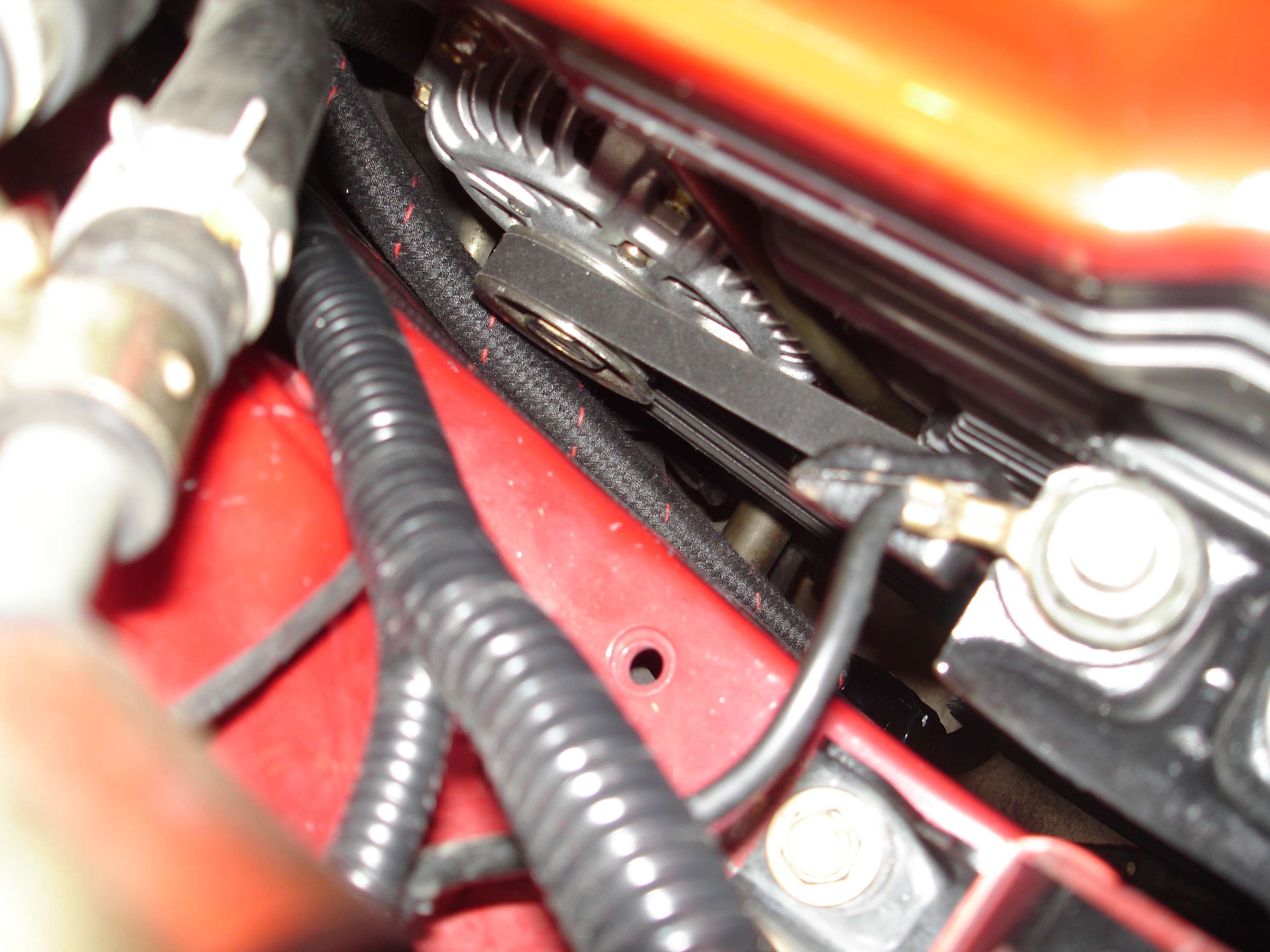
My hard to come by 1/2" NPT tap came in from ebay, so I drilled and tapped the intake manifold for the PCV vacuum line:
I tried about 9 times to get this right, couldn't get the camera to focus on the deep part of the manifold, macro or not. So, you can see my Haltech IAT sensor, and the PCV bung.
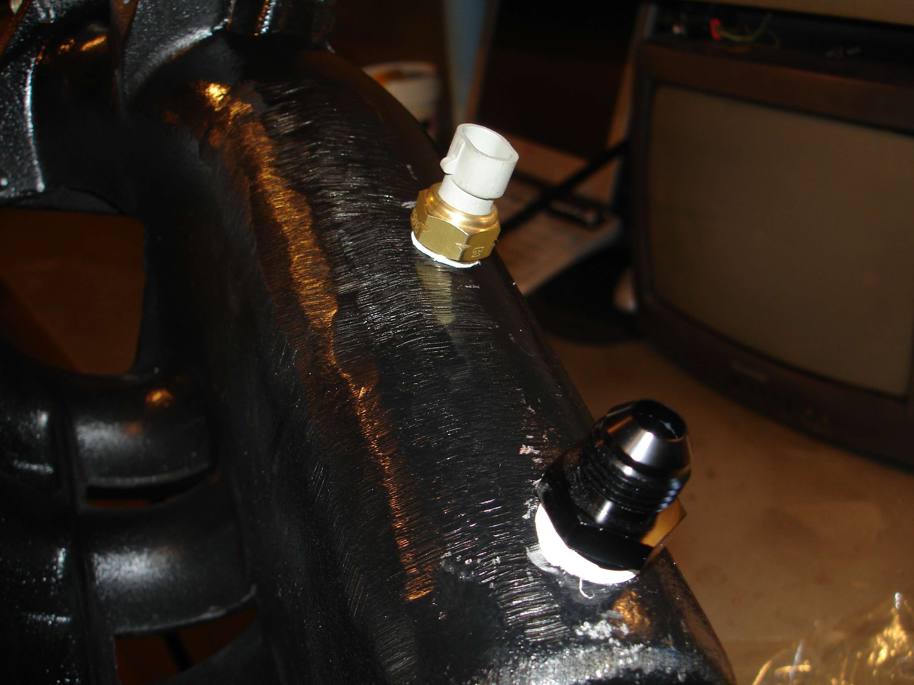
External view of both on the bottom of the intake manifold:
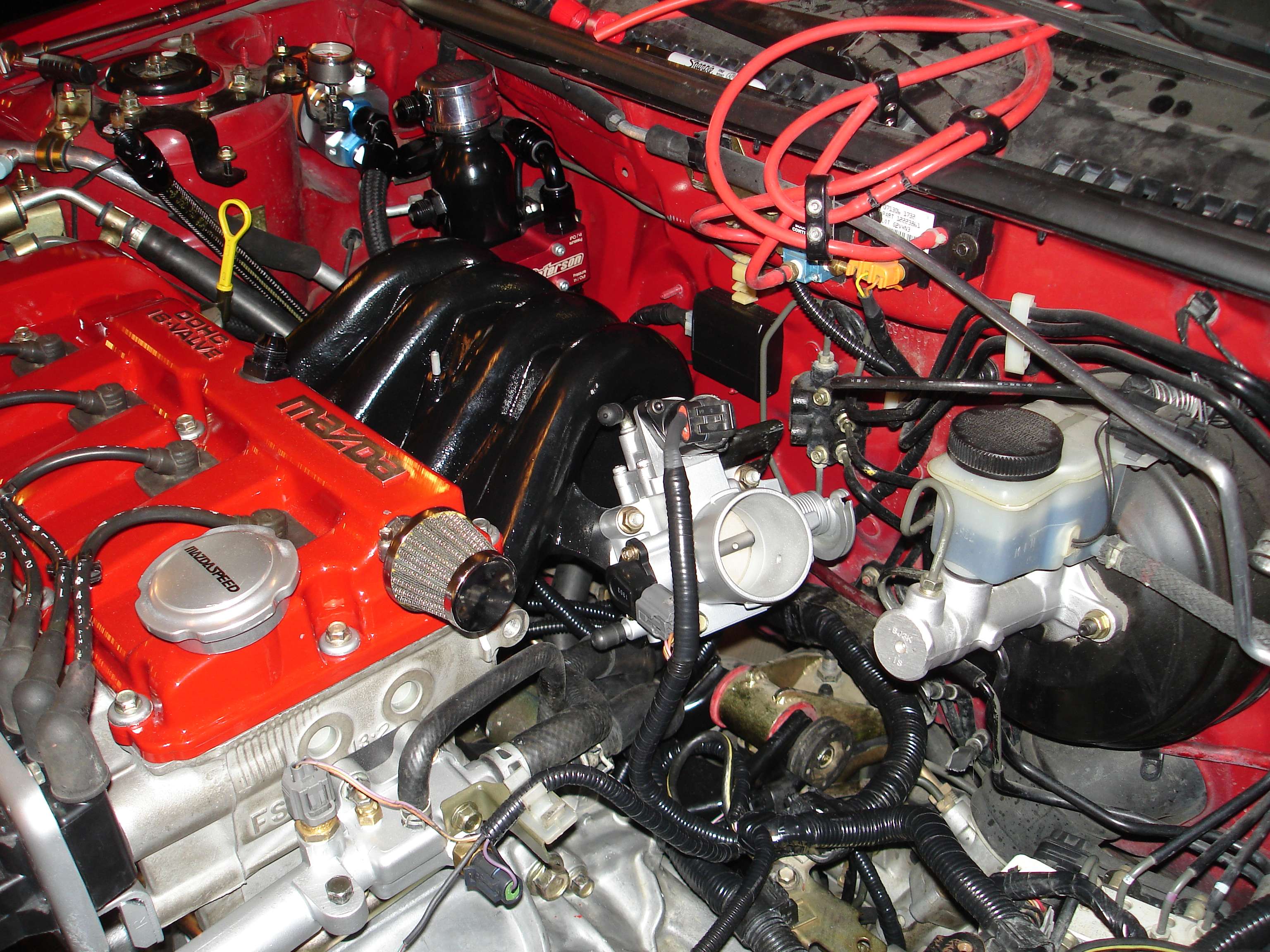
Test fit of the manifold. As I had hoped, everything is hidden and looks stock! (Espesially that IAC!)
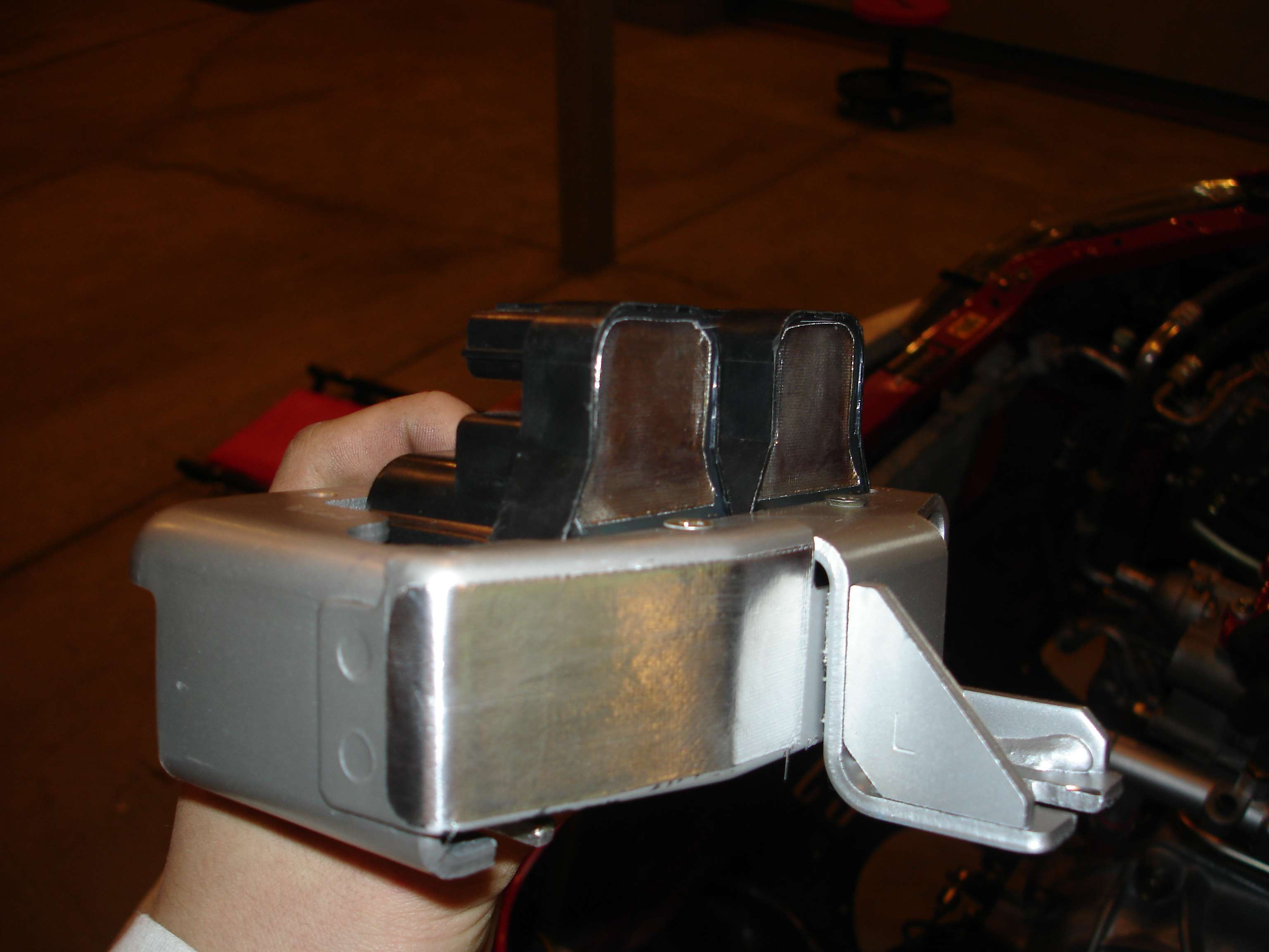
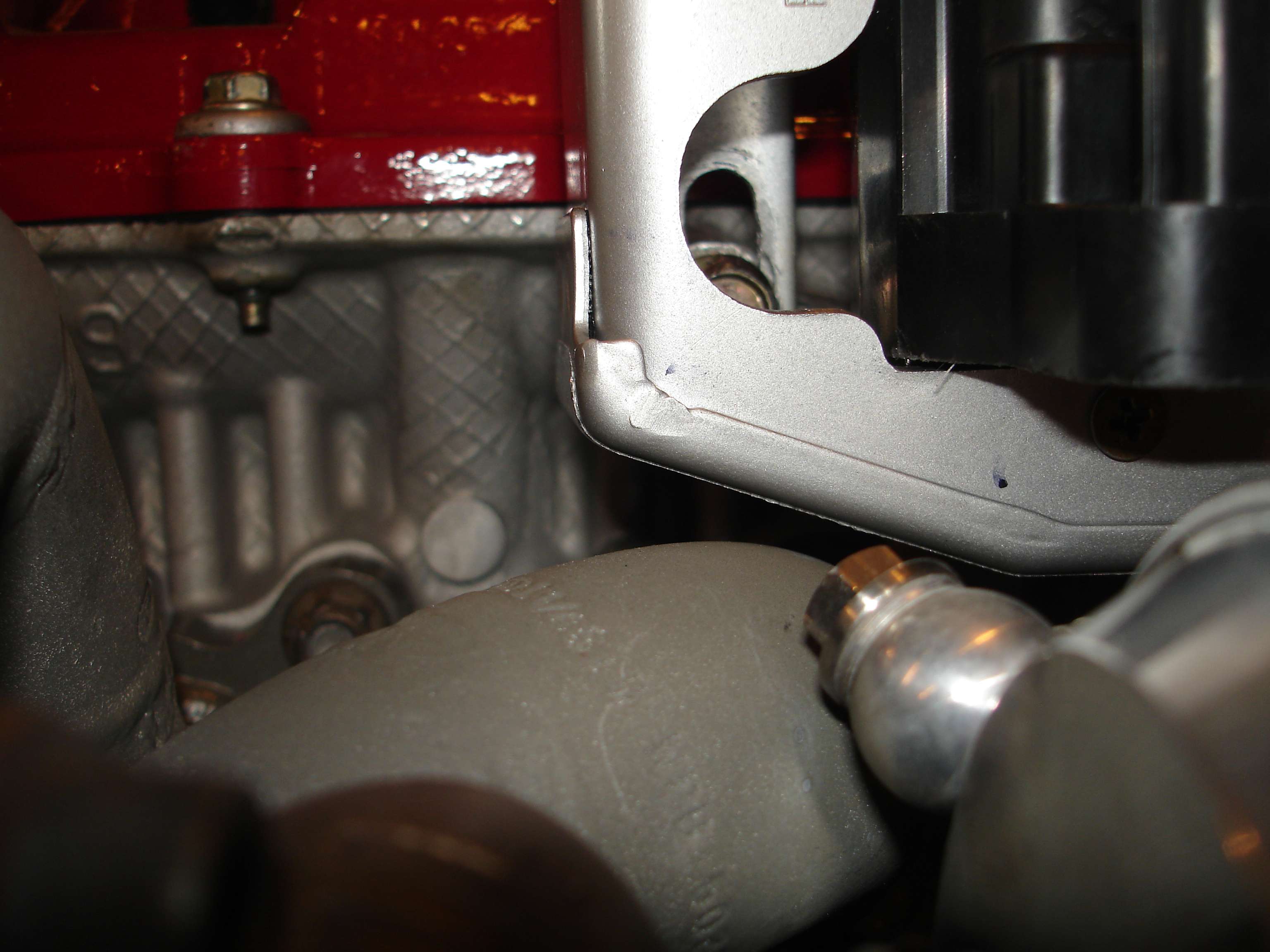
Got the coils installed, and new wires. Do you have any idea how hard it is to find black plug wires for this car? Everything was either blue, grey, or yellow. I could have gone with red Magnecor ones, but I thought that would be a little much. Had to modify the coil bracket slightly as well to clear my turbo manifold. It's still close, so I'll install some heat shielding on the underside of the bracket.
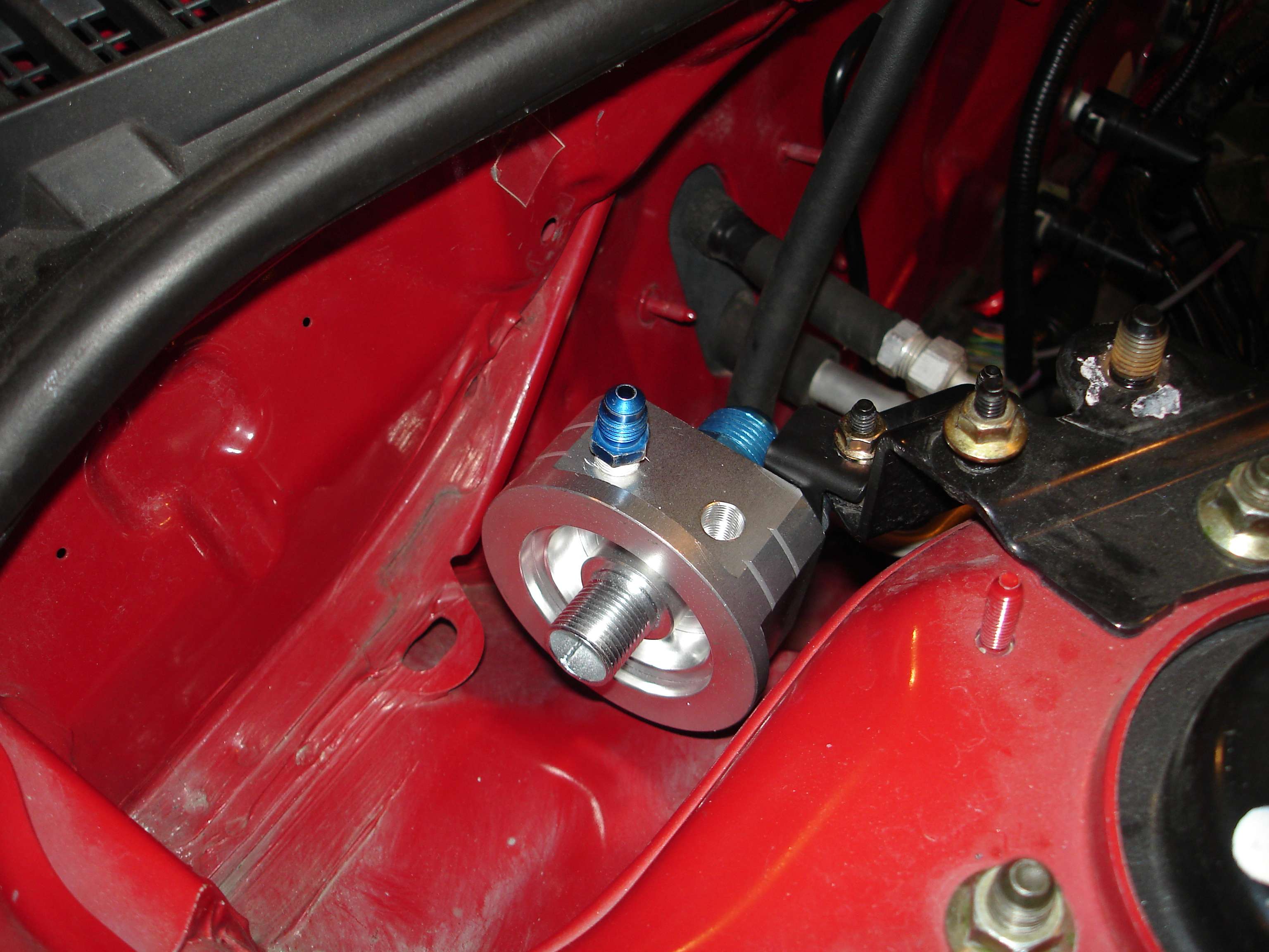
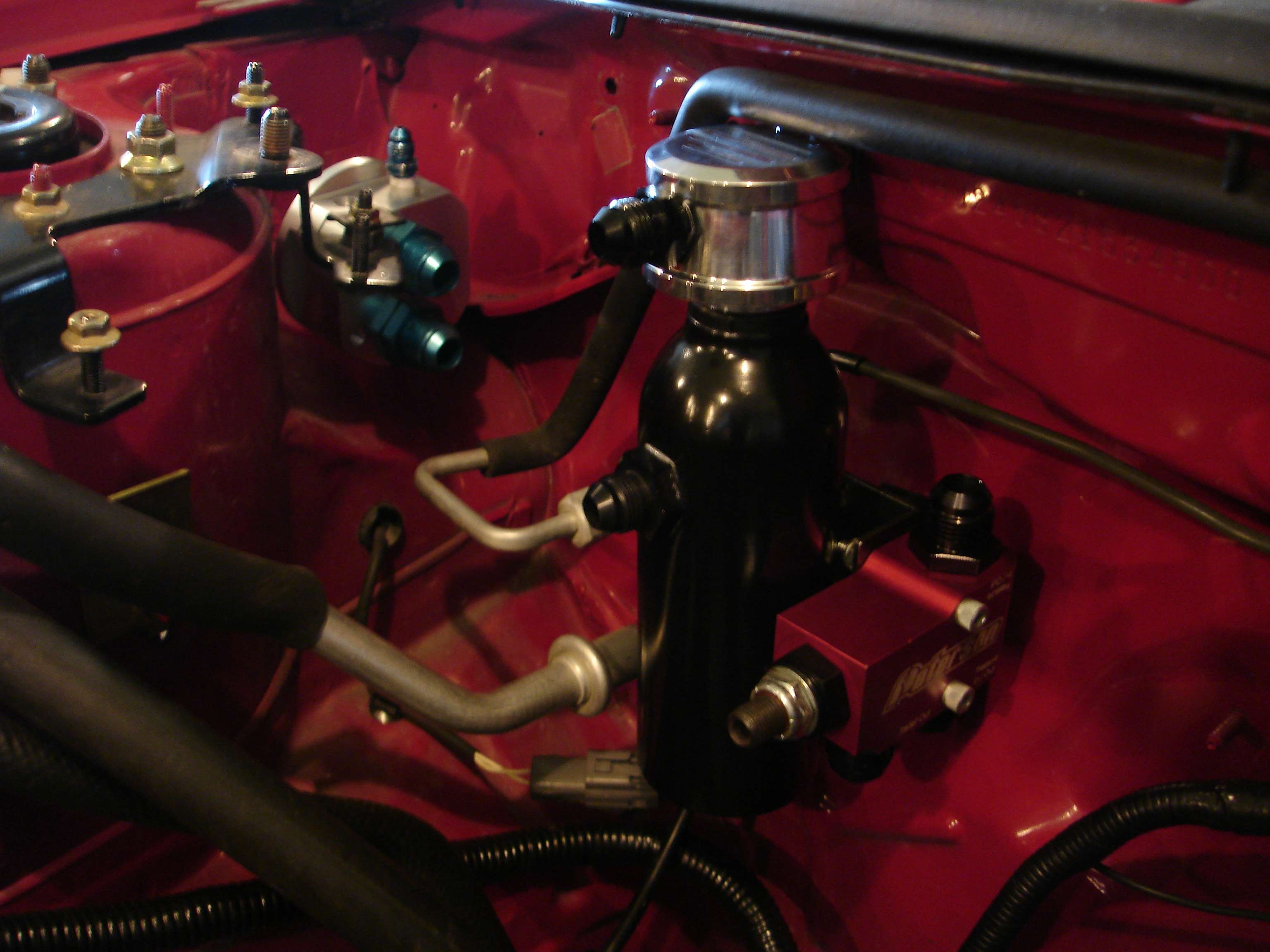
Now comes the fun stuff! Had to get this entire oil system laid out, it was driving me nuts. Mounted the remote filter adapter up by the strut tower, so it's not a bitch to change. The blue nipple seen there will be the turbo oil feed, and the other open port will house a secondary oil pressure gauge, so it's right under the hood for me to see when I set the external pressure regulator. I had to fab up a bracket to mount it where my cruise used to be. Believe it or not, stuff like that takes close to an hour:
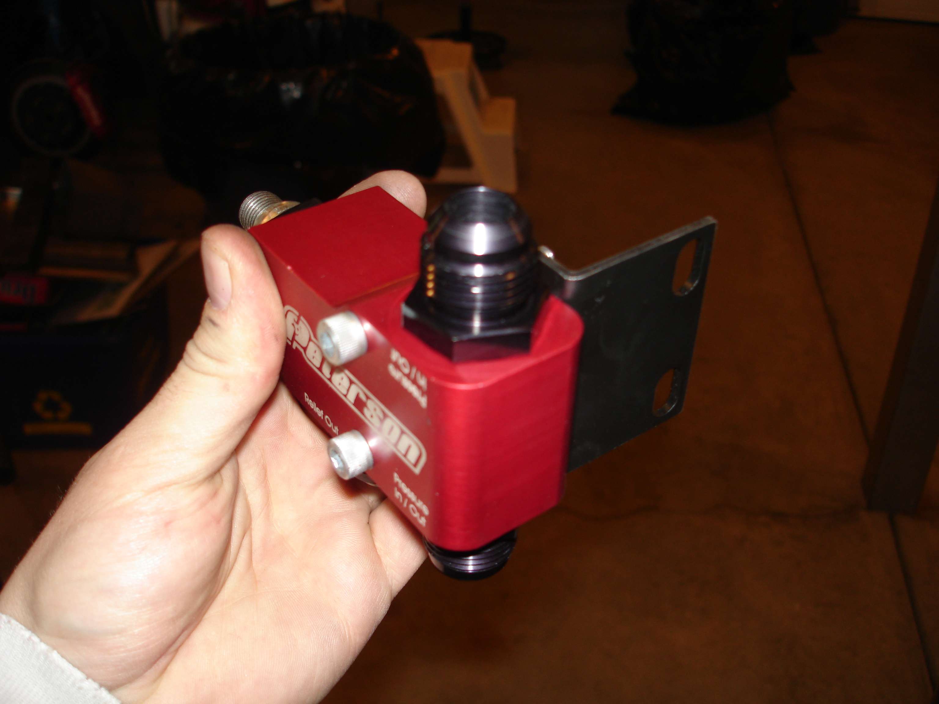
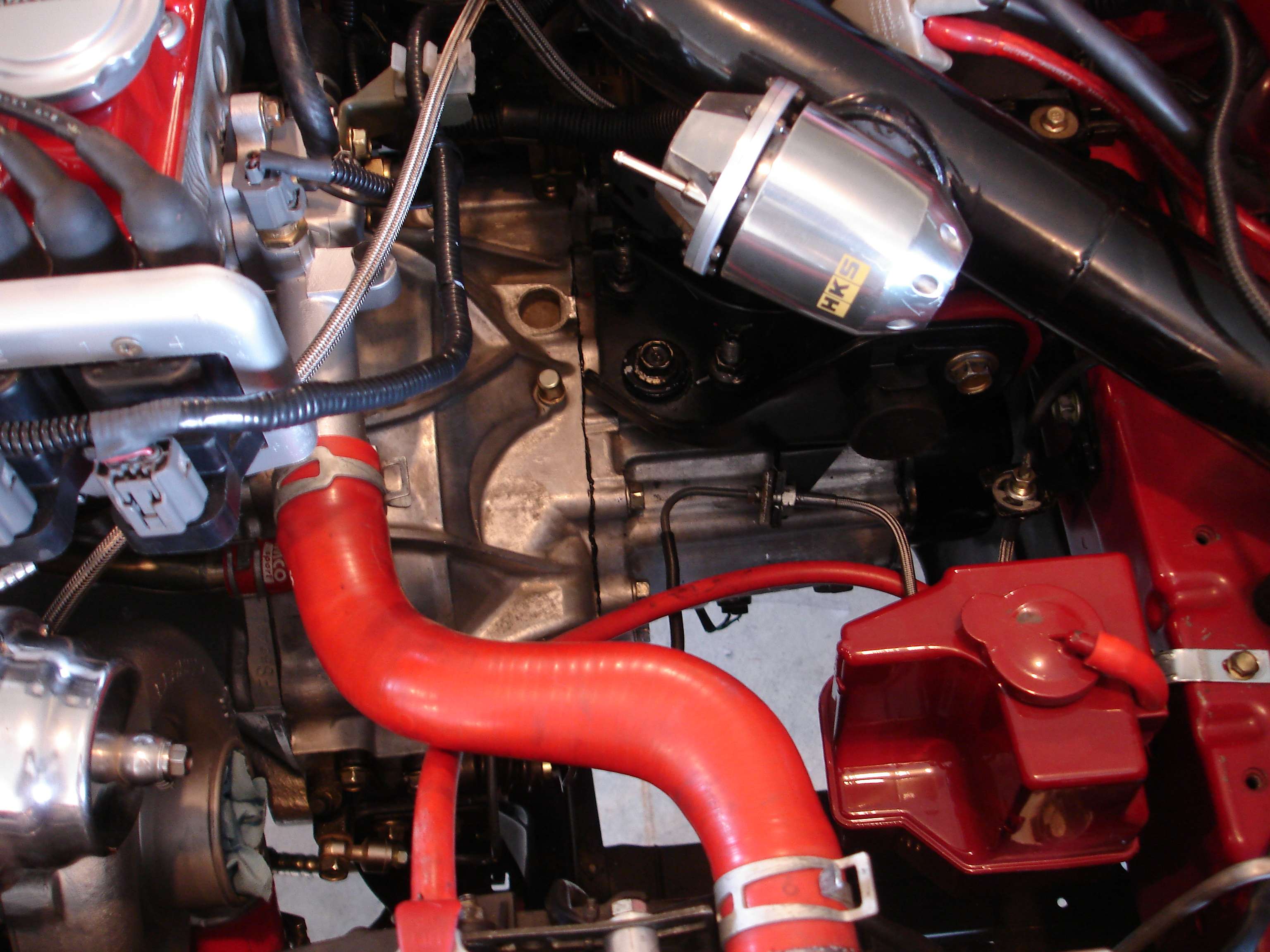
After building another bracket to mount my new sealed catch can, I was struggling to find a place to mount the external PRV. I needed it to be sano, but still somewhere that I can access it realatively easily. On a stroke of genius, I decided to fab up yet another bracket:
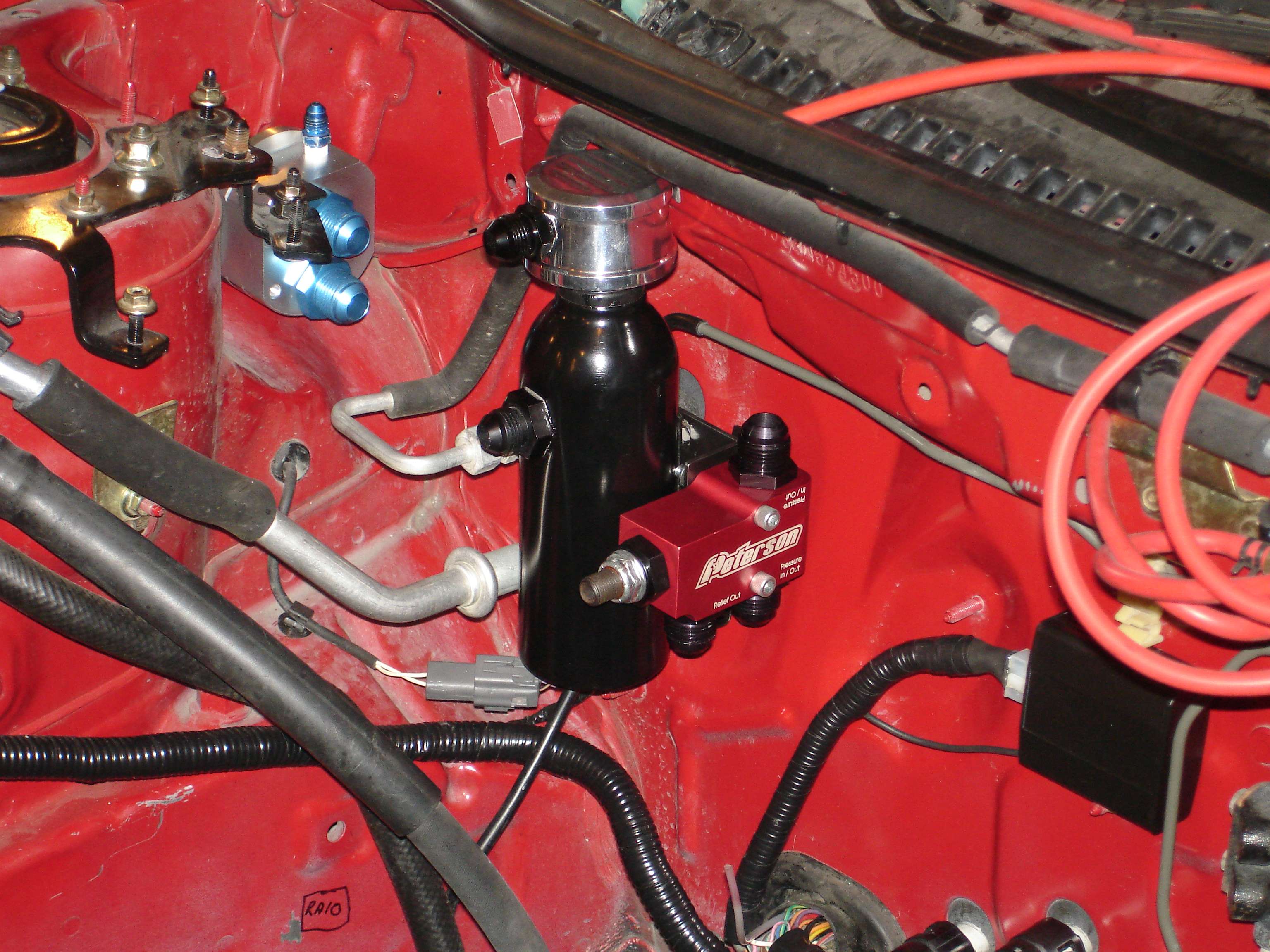
...And mount it alongside the catch can!
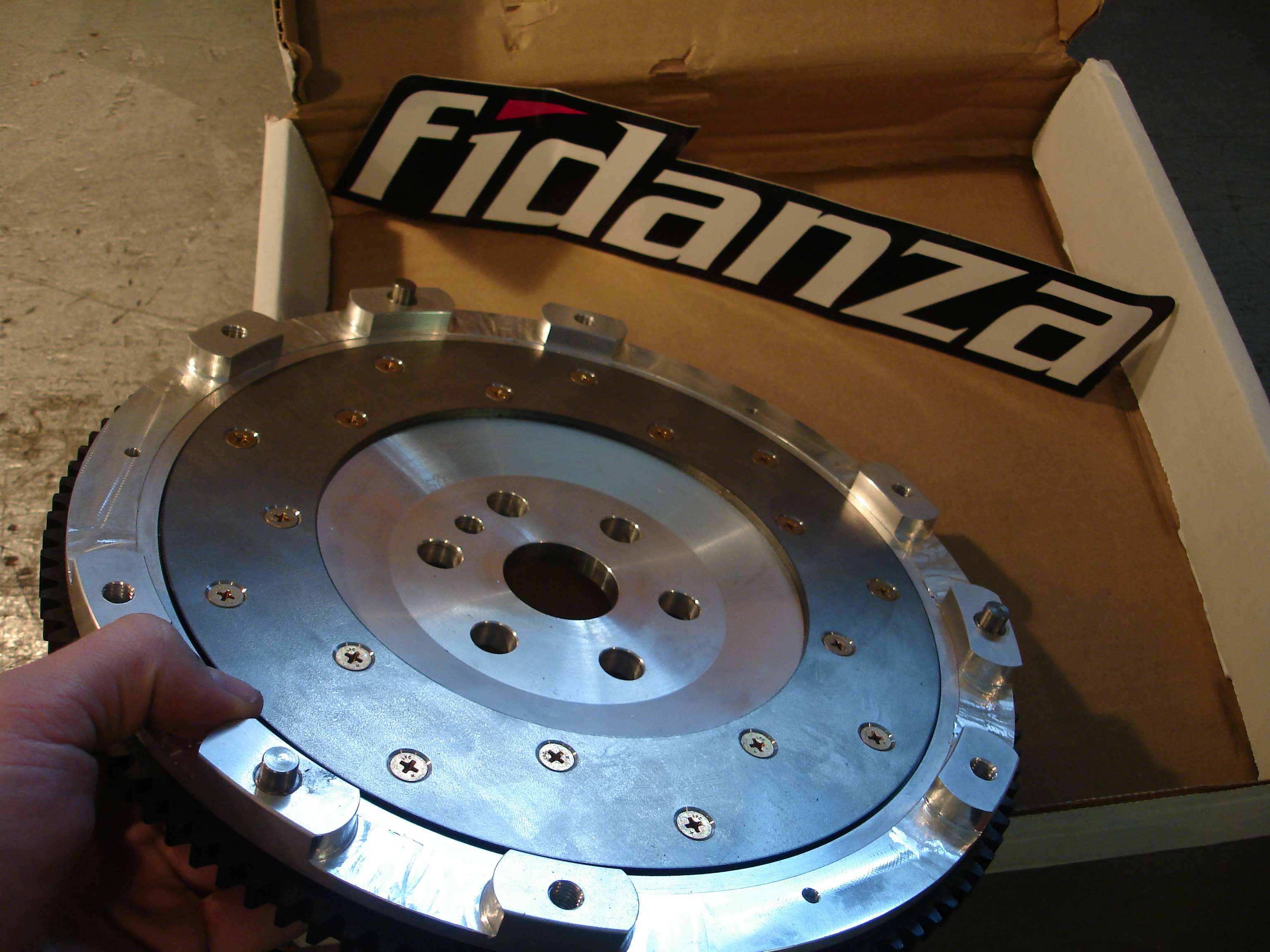
Also, got my Fidanza 7lb flywheel today:
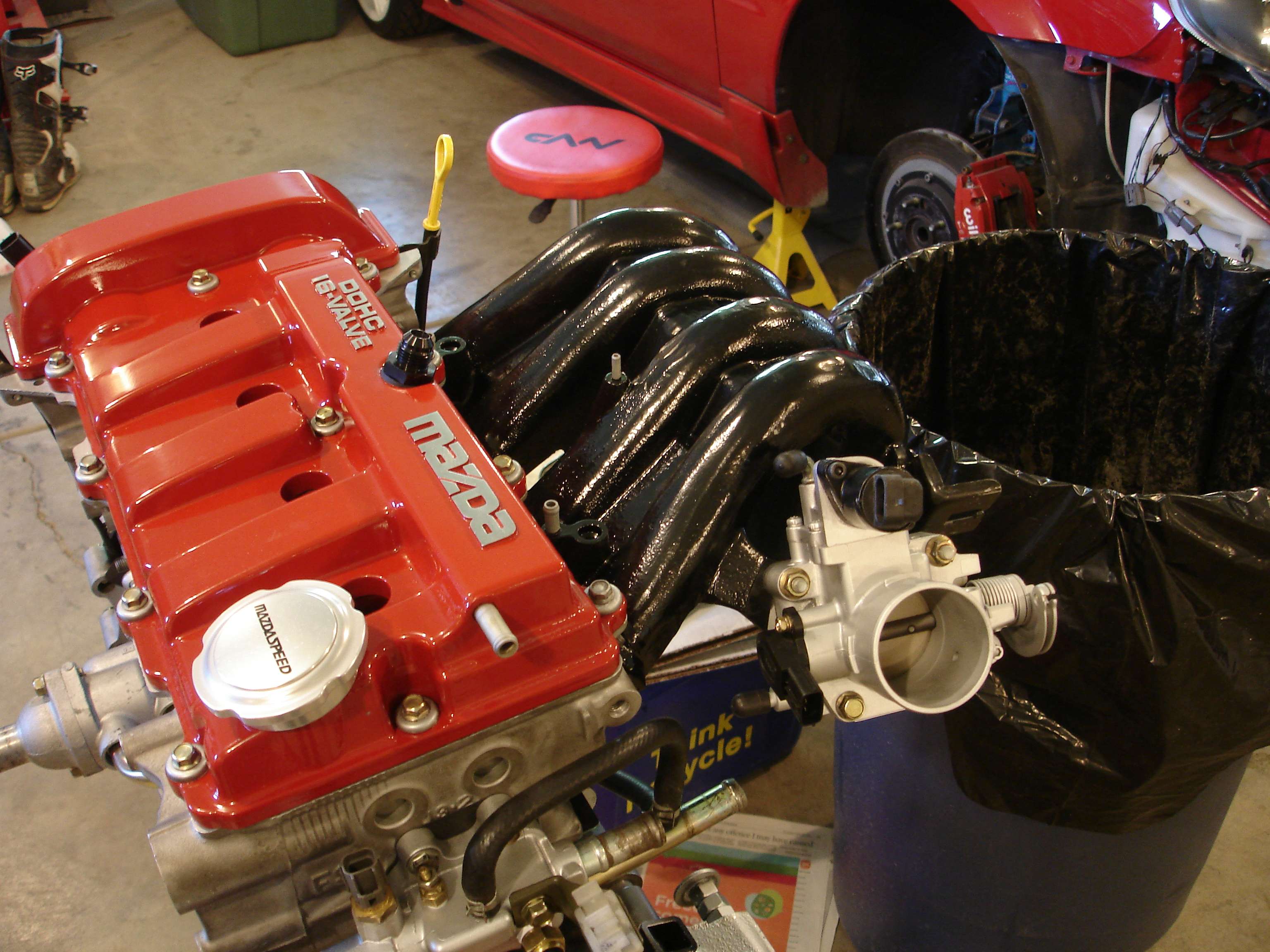
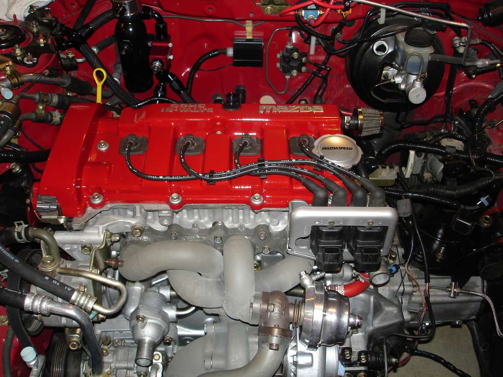
And finally, one last shot of the engine:
So the ACT clutch that I ordered is on backorder (note to sellers, I should not have to call you to find out why my shit hasn't been shipped yet. Thanks for wasting a week of my time...) So I called ACT, and it's on backorder from them for 4-6 weeks. A call to Clutchmasters had a brand new FX400 6 puck on it's way to me for Friday delivery here in Canada. (Shipping ALONE was $190!)
I originally wanted a CM clutch anyways, but found an awesome deal on the ACT, so I went with that. Moral of the story, always stick with your first choice!
...
Registered User
Well, my clutch showed up today. Overnight from Japan.
Seriously though, overnighted from California. HUGE props to the guys at ClutchMasters for getting this together and shipping it out so quickly!
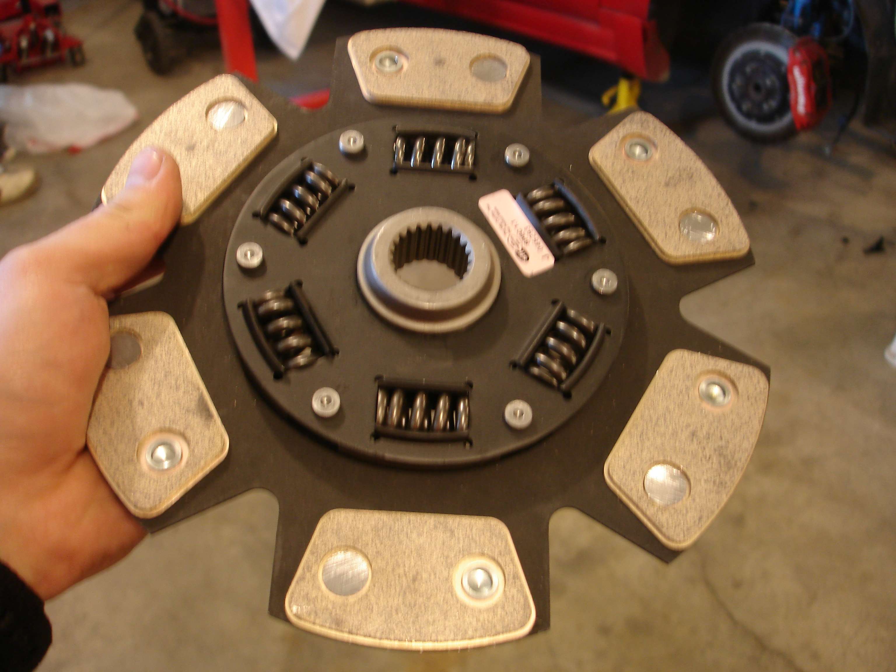
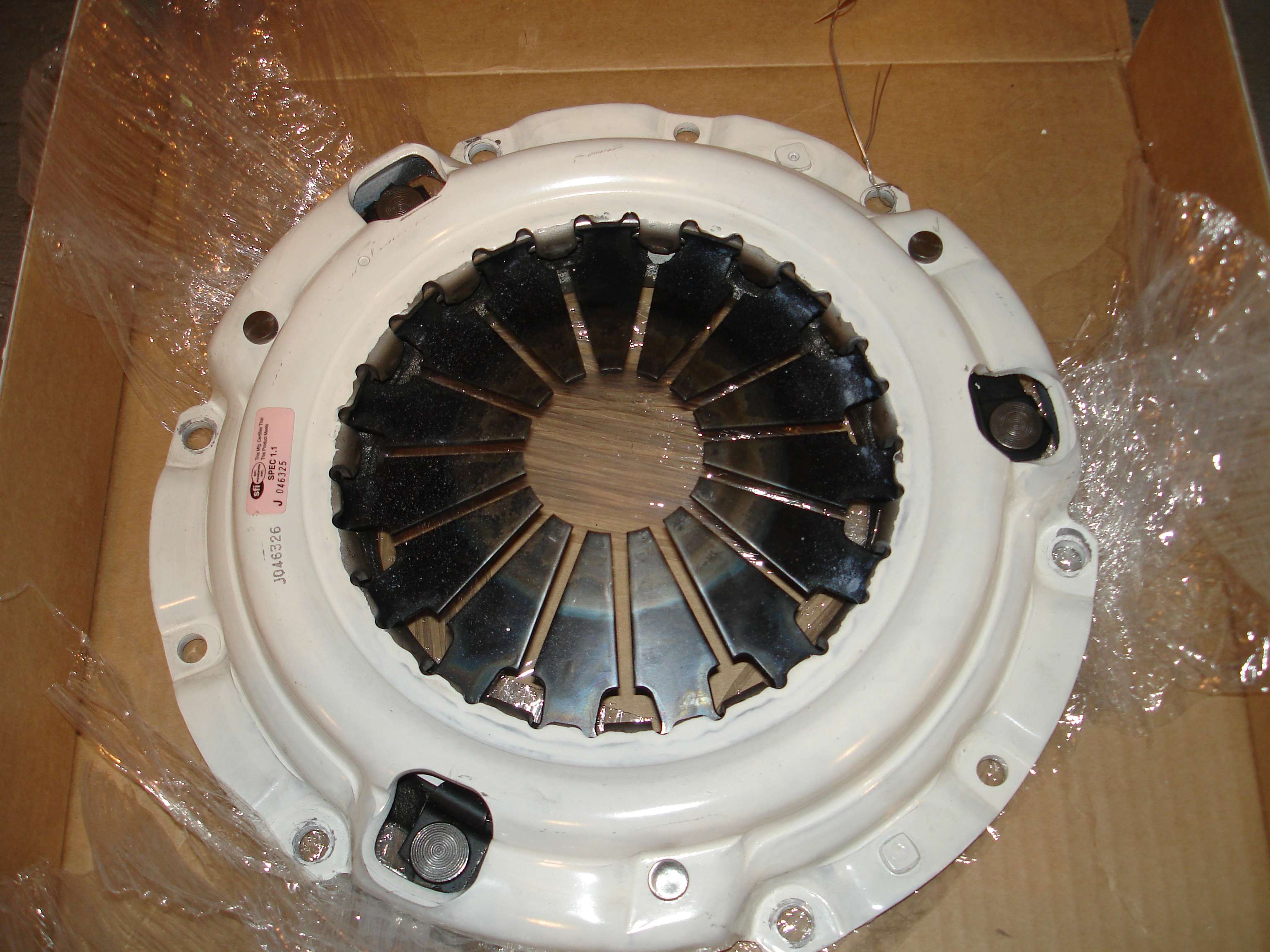
Here it is, the FX400 6 puck sprung race clutch:
Heavy duty pressure plate, good for 470Lb ft. If this thing starts to slip on me, I've got bigger problems than a clutch.
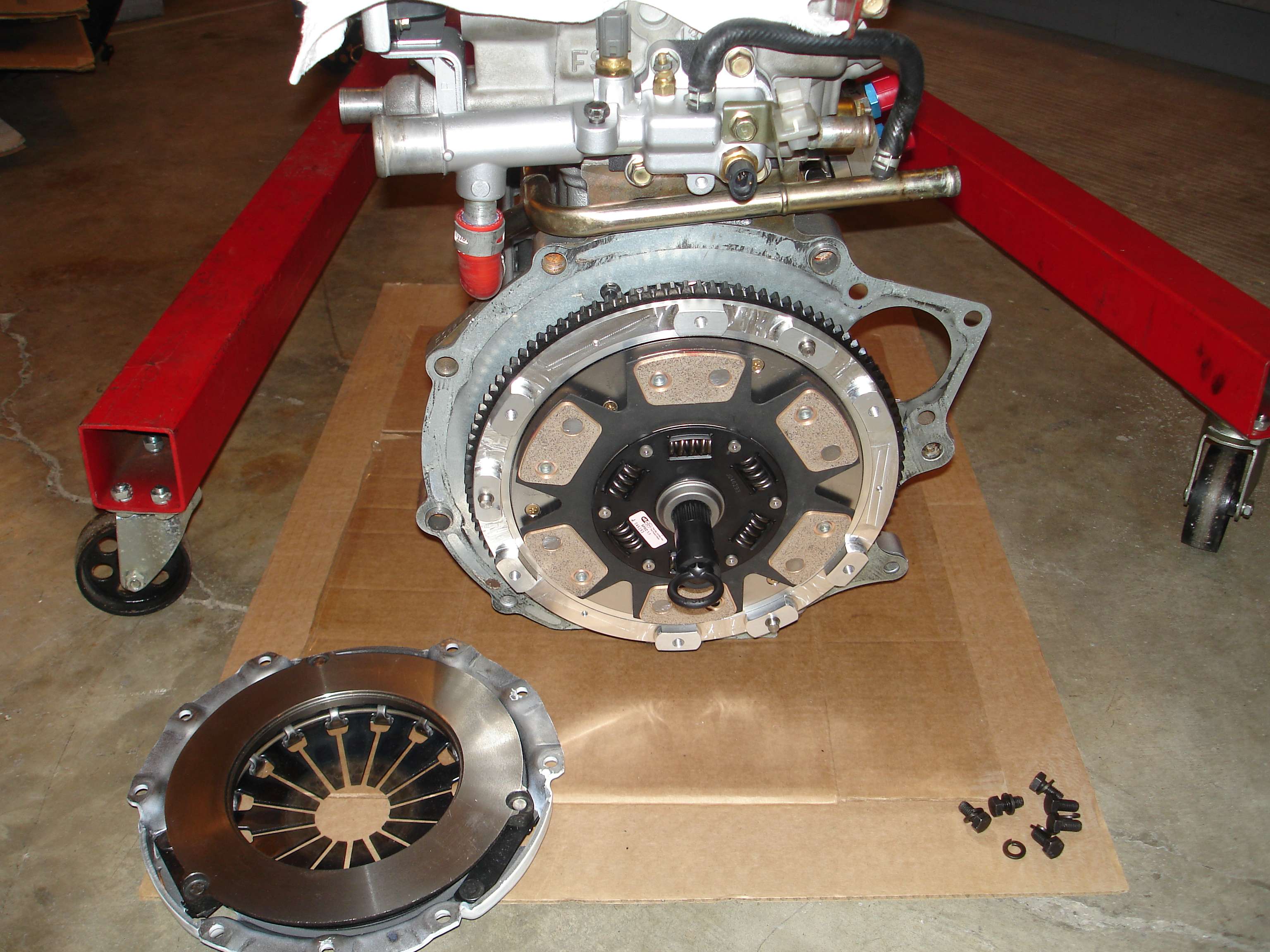
Fidanza flywheel on, cleaned and torqued, adapter plate on, and clutch disc on and centered.
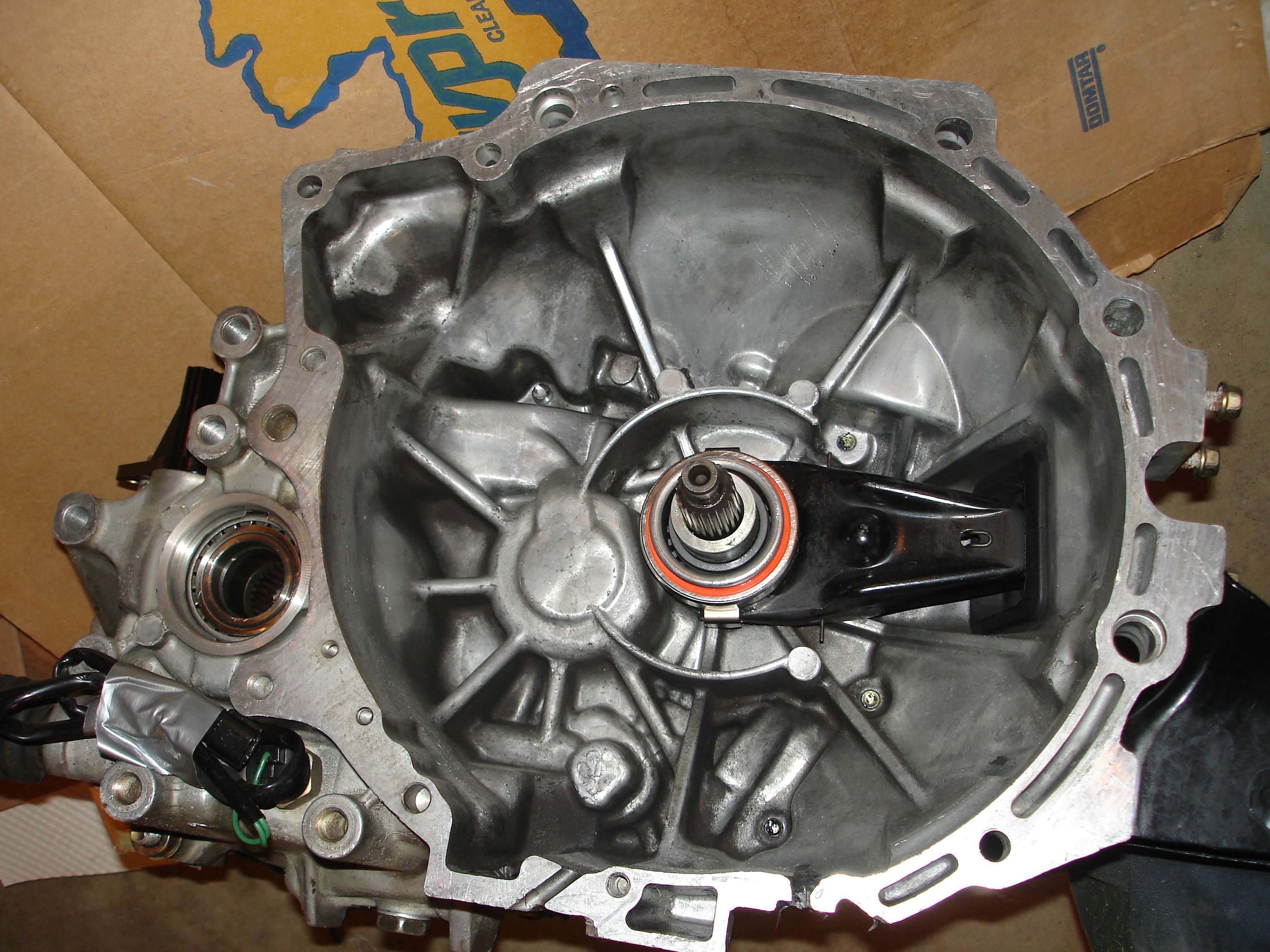
Throwout bearing installed and greased:
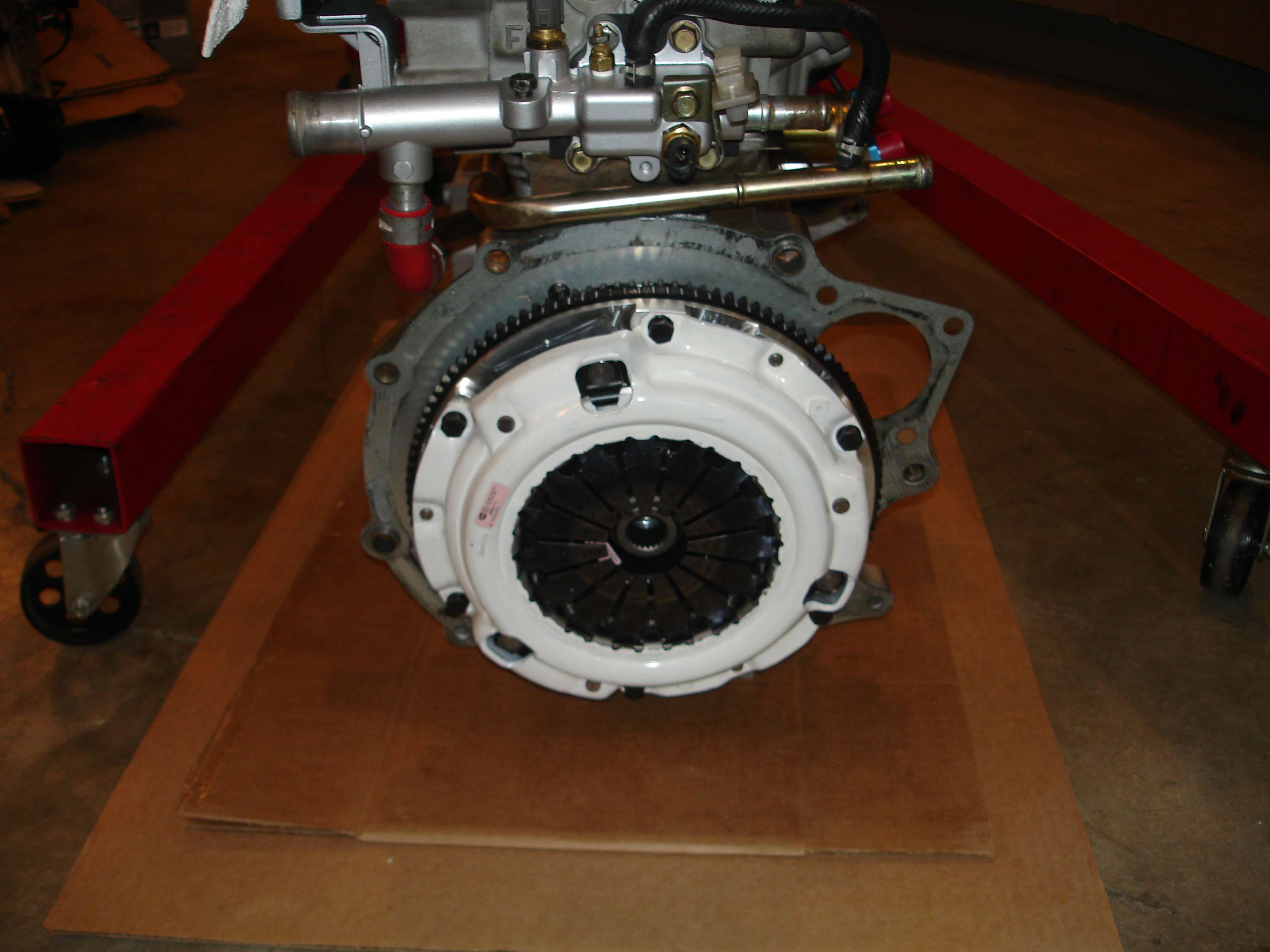
Here she is torqued down:
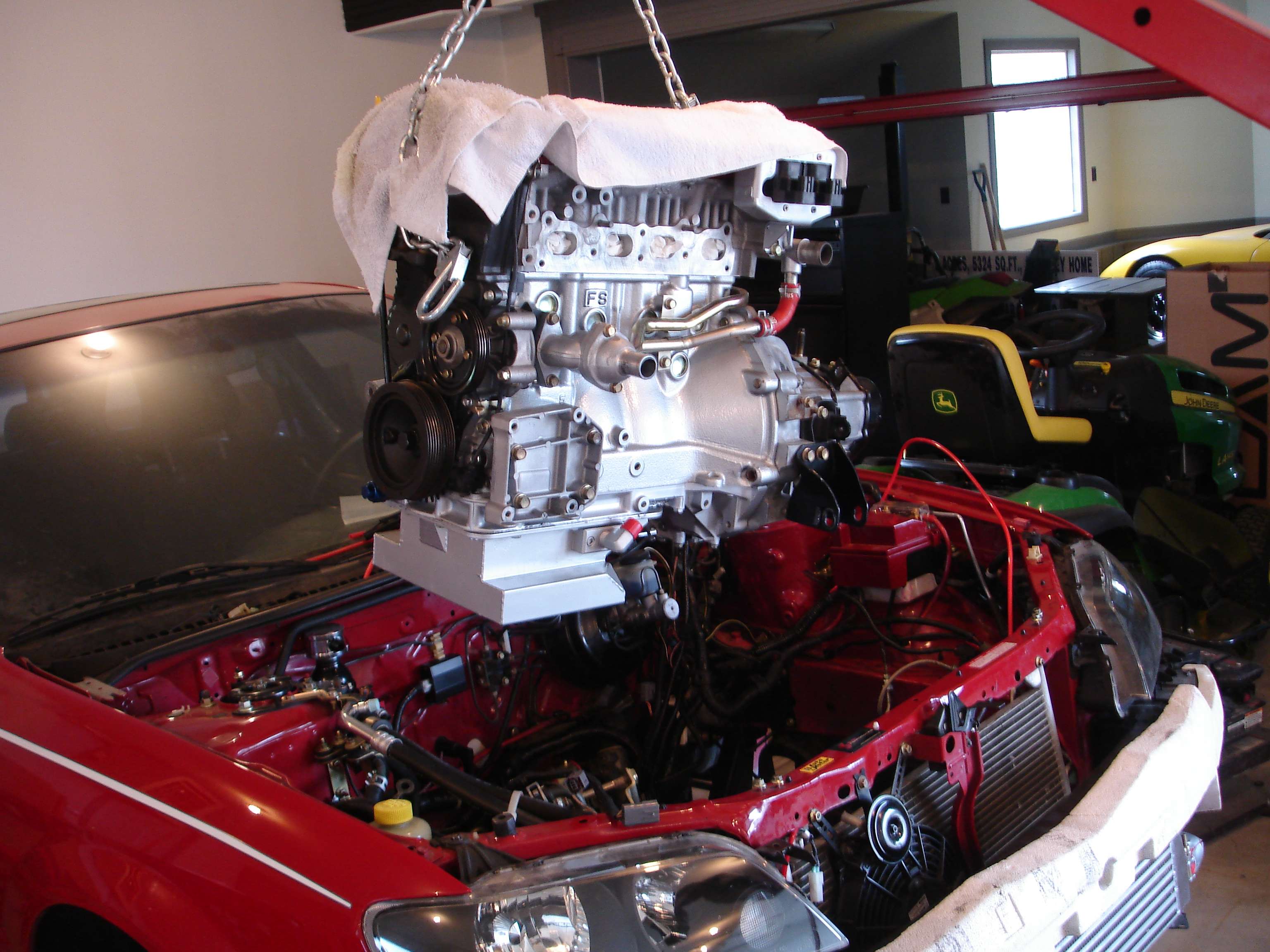
Transmission on, the engine is ready to go back into the car:
Up and over:
And, may I present, for the first time since August 8, 2008 (Just realized, 8/8/08. Huh...) The engine is back in the car!
As they say, it's all downhill from here!
...
Registered User
amazing build man. Took me 20mins to read everything from start to finish. great inspiration!
Registered User
This thread is awesome, nice work!
Registered User
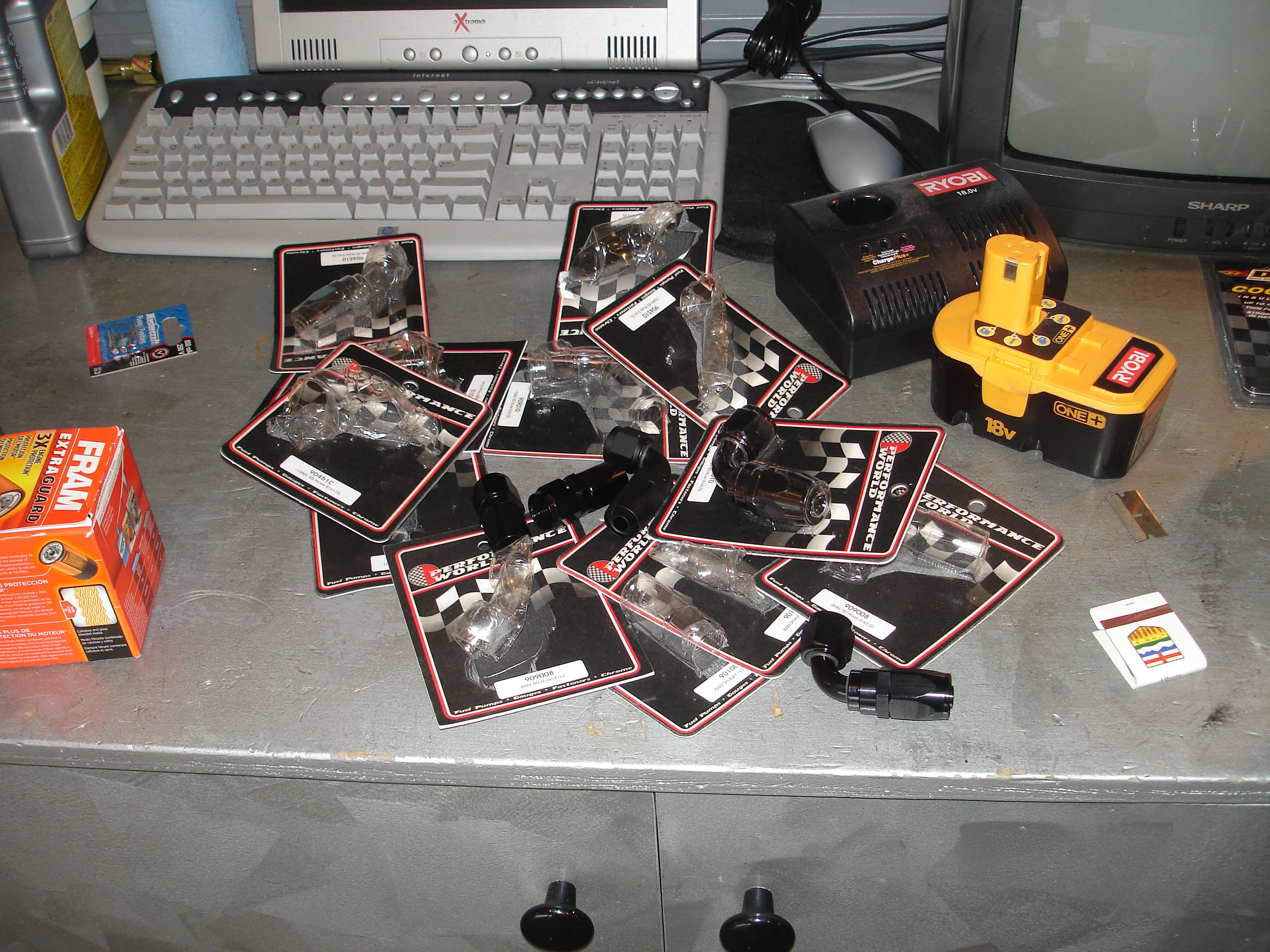
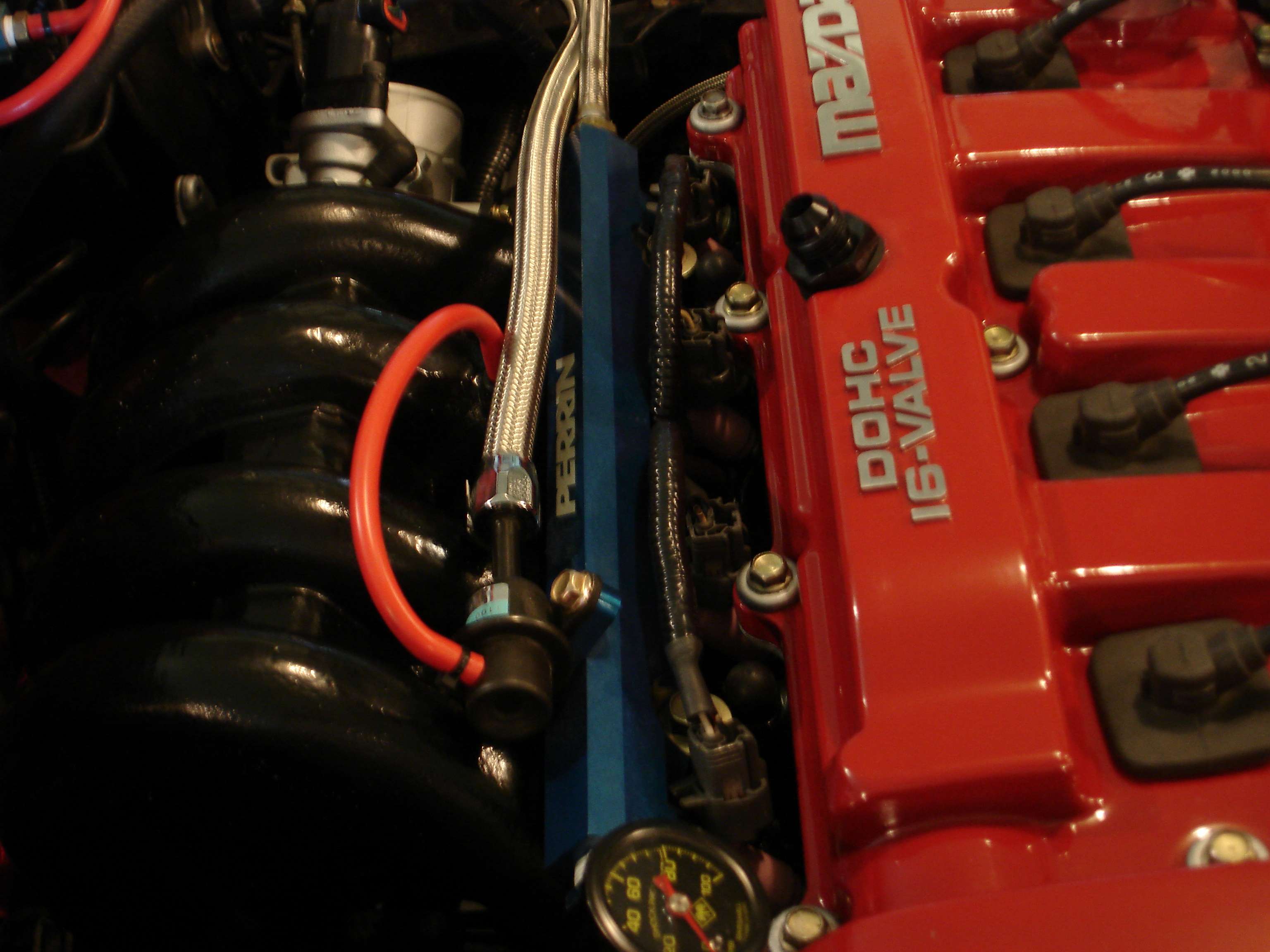
Started to plumb the oil system tonight. $400 worth of braided line and AN fittings. This is just about all the fittings:
Rather than stainless braided line (fugly) I went with some black fabric braided stuff. The Red accents look nice too. Started by mocking up the fittings, then cutting and running the lines. Everything is only finger tight, will be gronched down tomorrow:
The oil comes OUT of the block, IN to the bottom of the regulator, OUT the top of the regulator, IN to the bottom of the filter adapter (see note below) OUT of the oil filter, back IN to the engine. Hope that makes sense. Excuse the dusty engine bay. Sitting without a hood for two years will do that.
NOTE: It is VERY important that you get the lines right on your remote oil filter adapter. They are directional! Putting the lines in backwards will cause the backflow preventer in the filter to stop oil flow, and starve your engine of oil! This is why I did not run the line IN to the top of the filter adapter which would have looked nicer I'm sure.
Not run yet, there will be a line OUT from the regulator, IN to the windage tray for the excess pressure relief.
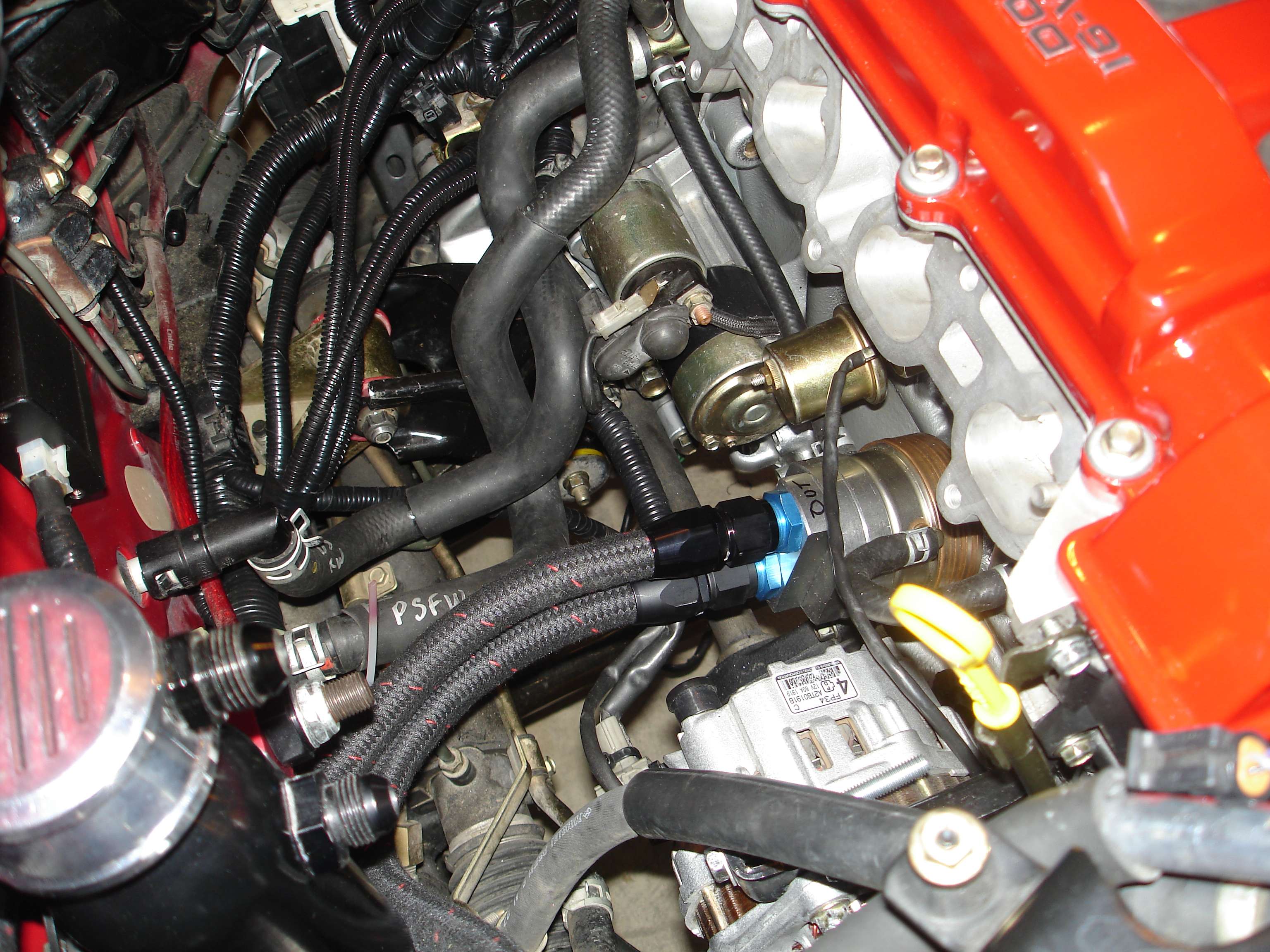
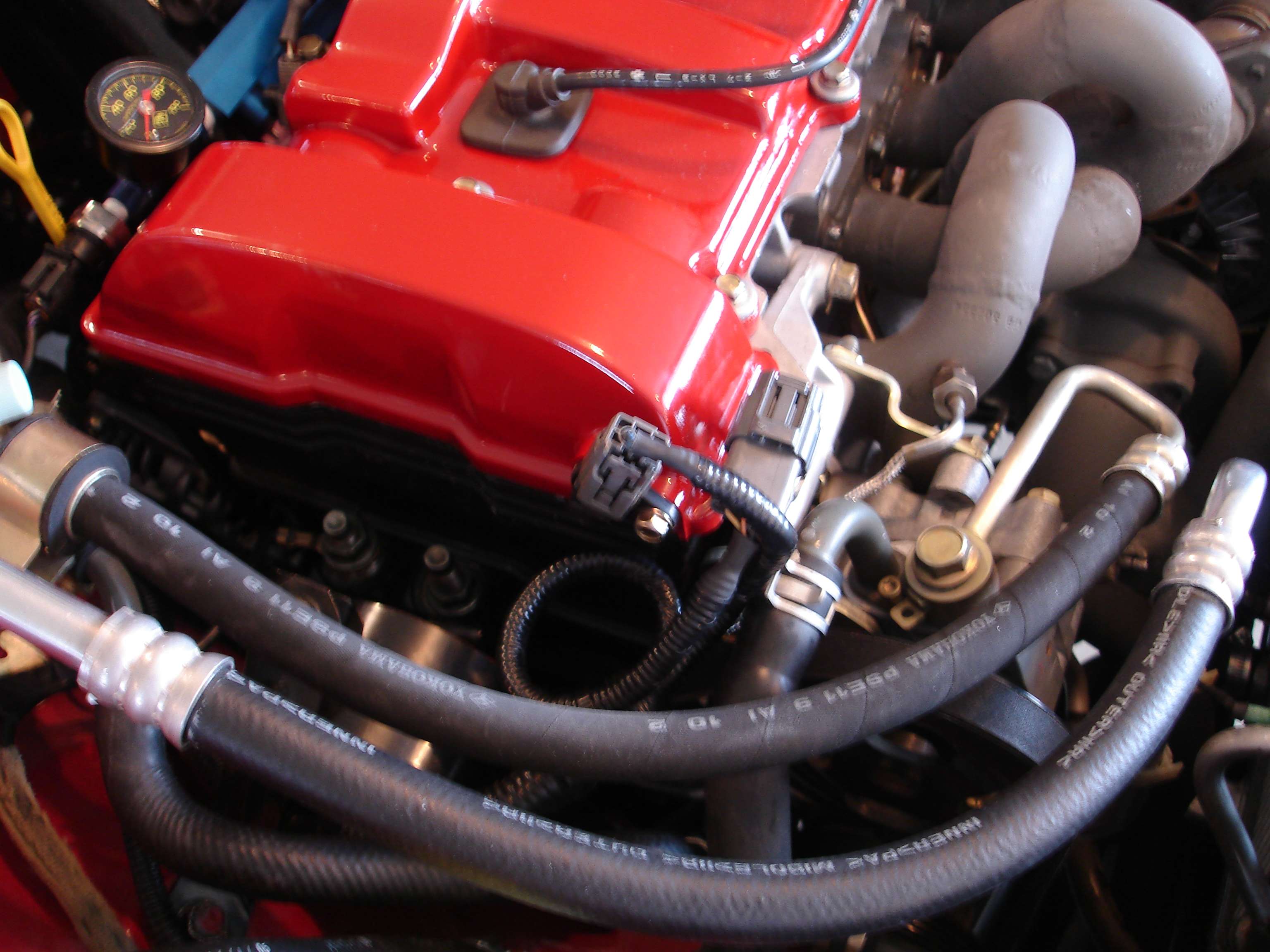
With the intake manifold on, there is lots of clearance. The hoses fit in between the IAT sensor and the PCV bung:
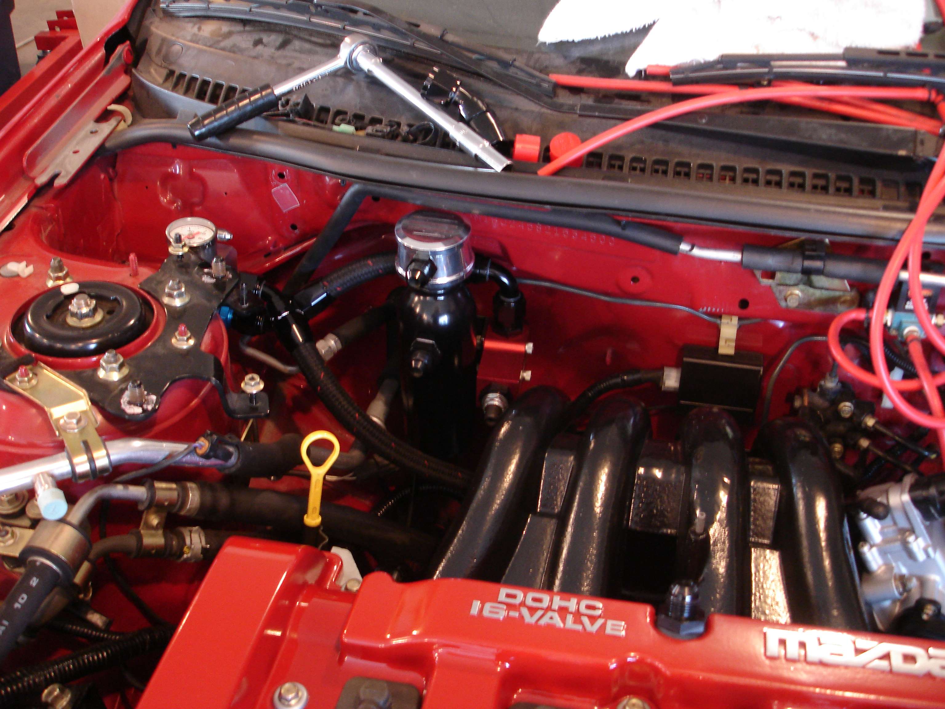
Without the flash, so you can see that everything looks very clean, and tidy. The pressure regulator is nice and easy to get to, as are the catch can and oil filter.
Tomorrow will be a BIG day as far as progress. Stay tuned!
...
Registered User
Well, made some SERIOUS progress today. I'd say the car is now about 90% complete.
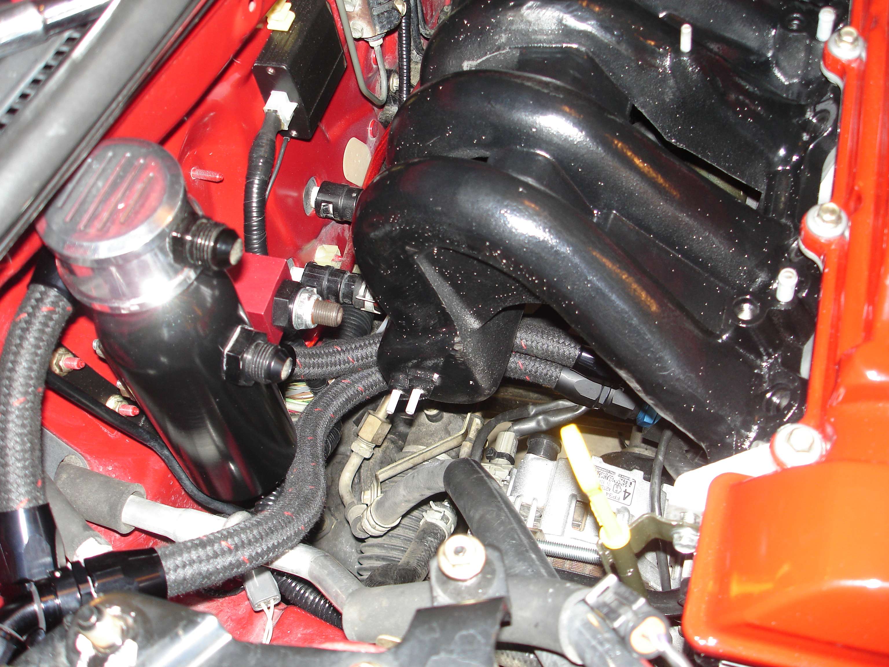
Finished the oil system, got everything plumbed and tightened down. Here's a shot of the bypass return ot the windage tray:
Up the side of the engine. It looks much closer than it actually is, there is a good 2.5" between the hose and the belt.
So, I suppose now is as good a time as any to finally take the wraps off my complete rewire, and explain it a little bit. There is one main "Trunk" line, with 3 main "branches" off of it. The main trunk runs left to right, along the firewall. One branch is on the passenger side, and includes the cam sensor, crank sensor, EGT probe, fuel pressure sender (these all terminate at the engine) and then continues on to the front bumper area housing the A/C clutch wire, methanol pump wiring, etc.
What I call the "center branch" gomes out of the trunk directly behind the engine. This is a busy branch containing wiring for the injectors, coils, transmission, IAC, TPS, oil temp, oil pressure, water temp (stock, autometer, and Haltech) haltech IAT, wideband and narrowband, etc. The intent of having it come out directly behind the engine was to keep everything hidden, and as you'll see I think it was a success. The third branch is o nthe driver's side, and ties into the fuse box, battery, etc. A standalone fuse panel was added for all interior accessories (see first page.)
I relocated alot of sensors and harnesses where I could, basically rewired the entire engine bay. As you can see, it's MUCH cleaner now. Trans area:
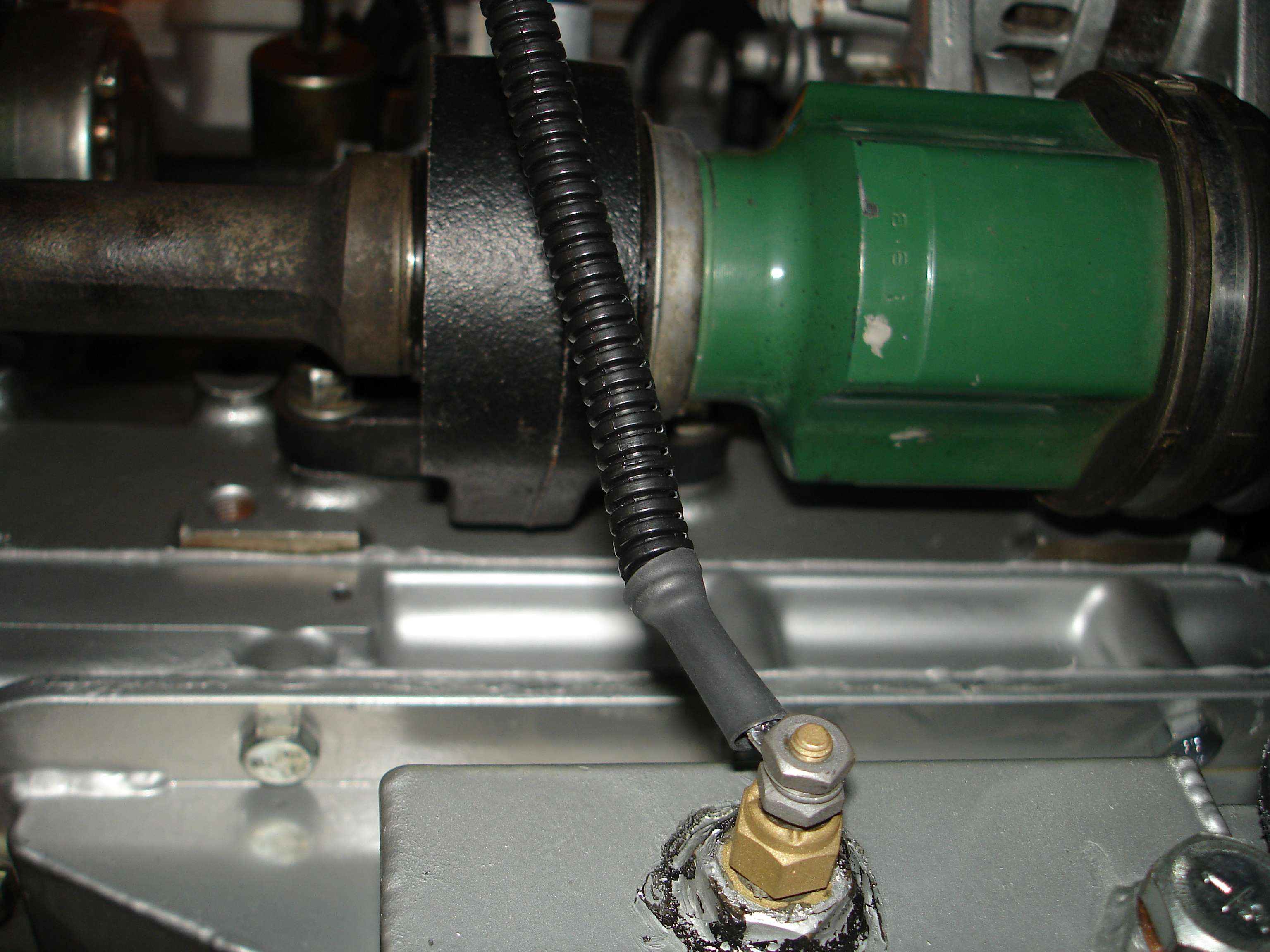
Oil temp sensor:
Here the coolant sensors are not finished yet, but you can see the "throttle body" loom with the IAC motor wiring and the TPS.
So, because the coils sit so close to the exhaust manifold, I used some DEI heat reflective tape just in case.
The turbo manifold and downpipe on and tight:
With a LOT more shit bolted up now, I was on a roll and didn't stop to take pics. Intake mani on, wires run (I'm STILL not happy with the coil wires. I'll either redo them or make a shield to hide them.) Rad in, fuel rail on, more shit plugged in...
The injector wires come up through the middle of the manifold, and split out, instead of running the length of the VC like stock. VERY clean and tidy. You hardly notice them anymore.
Fuel rail plumbed, rad overflow in, intake pipes on, electrics done, turbo oil feed run, battery in... WHEW! What a task all this was!
Like I said, rather than cuto ver the valve cover, the sensors are now run fro mthe passenger side, and everything connects at that one corner. Very neat and tidy:
Another shot of the injector wiring - or lack of it!
So, what's left? Well, I have a few more intercooler pipes to tighten up, then a few misc. things to bolt on, finish plumb the PCV system, bleed clutch, filld liquids, etc. Shouldn't take too long.
The goal is to turn the key tomorrow!
I have all fluids ready to go, a few oil filters, etc. I'm a little concernicus about all the changes I've made as far as the Haltech is concerned, getting it started might be a little tricky. That combined with my new IAC motor, the agressive cams, everything. I hope all goes well and that there are no leaks!
...
Registered User
Sorry for sounding like a newb, whats the thing wit the TAL letters attached to your exhaust manifold?
1968 Impala: Status: Stored
1977 Dodge Triple E RV: Sold
1989 Mercedes Benz 420 SEL: Sold
2008 Mercedes Benz C230: Cruising
2000 Bluebird TC2000: Build phase of skoolie project
2018 Rav4 XLE: New baby friendly daily
Registered User
"TiAL" actually, it's a waste gate.Originally posted by cycosis
Sorry for sounding like a newb, whats the thing wit the TAL letters attached to your exhaust manifold?
Originally posted by Grogador
Shoulda threw in a "no homo" somewhere... cuz... yeah...toexistphoto.comOriginally posted by turbotrip
seems like a recipe for rape
AMG Killer
crazy build for a protege!
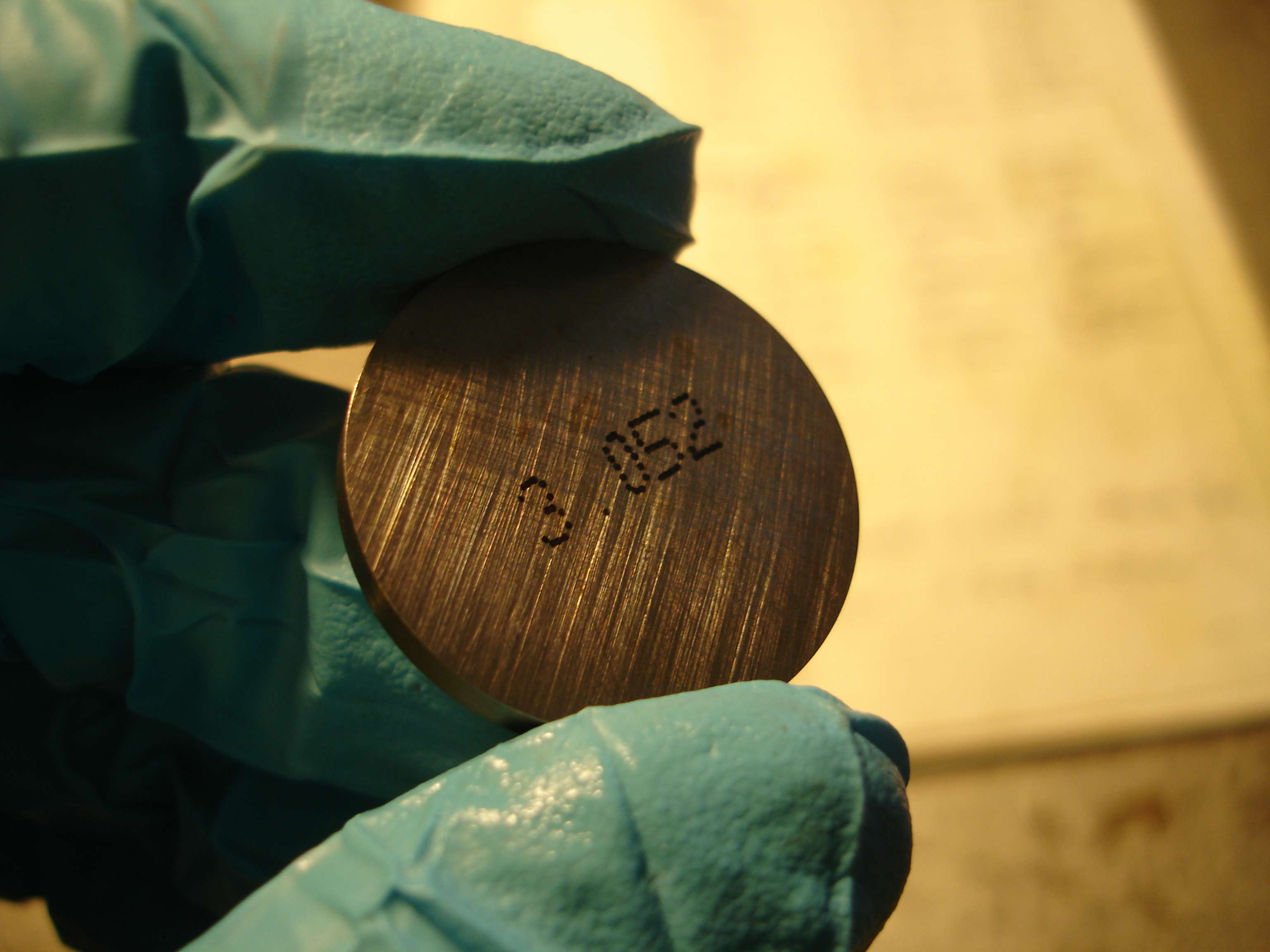
wanted to add that in no way can you accurately measure the bore of a cylinder with a caliper. i would guess you do know this
Machining, Fabricating, Welding etc.
Registered User
Of course. I do not have a dial bore gauge. The point of doing a quick check with the caliper was just to rule out any gross over or undersizing by the machine shop. I paid them to finish the bore to a certain diameter and they did. This was merely a confirmation of that fact. I think I even mentioned that in the post containing those pics.Originally posted by legendboy
crazy build for a protege!
wanted to add that in no way can you accurately measure the bore of a cylinder with a caliper. i would guess you do know this
...
Registered User
IT'S ALIVE!
Pics and details to come in the following days.
...
Registered User
Oh. My. God. Amazing work man. I can't imagine how satisfying it must feel to start it up for the first time.
Registered User
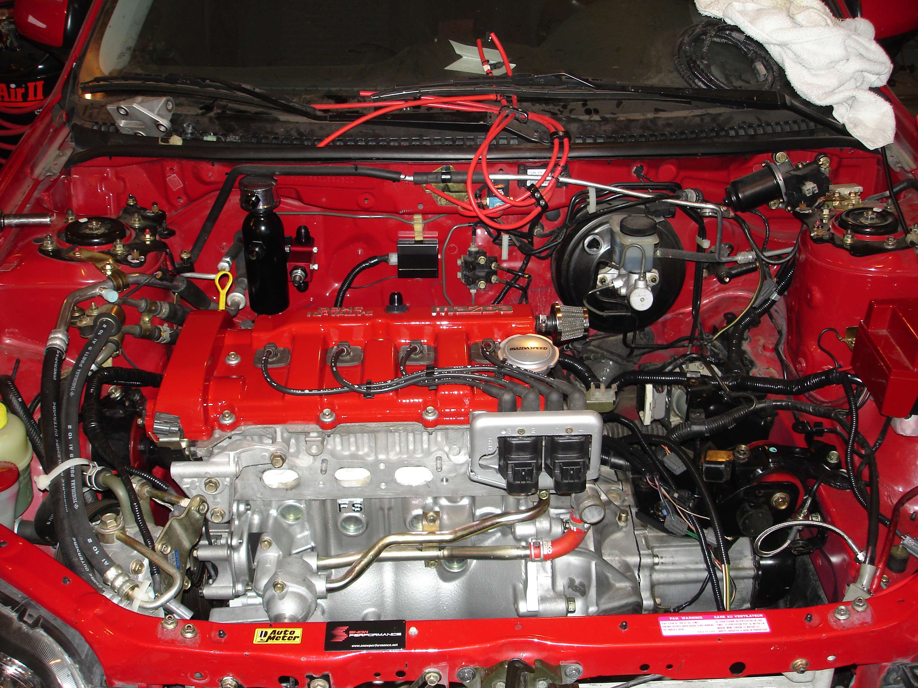
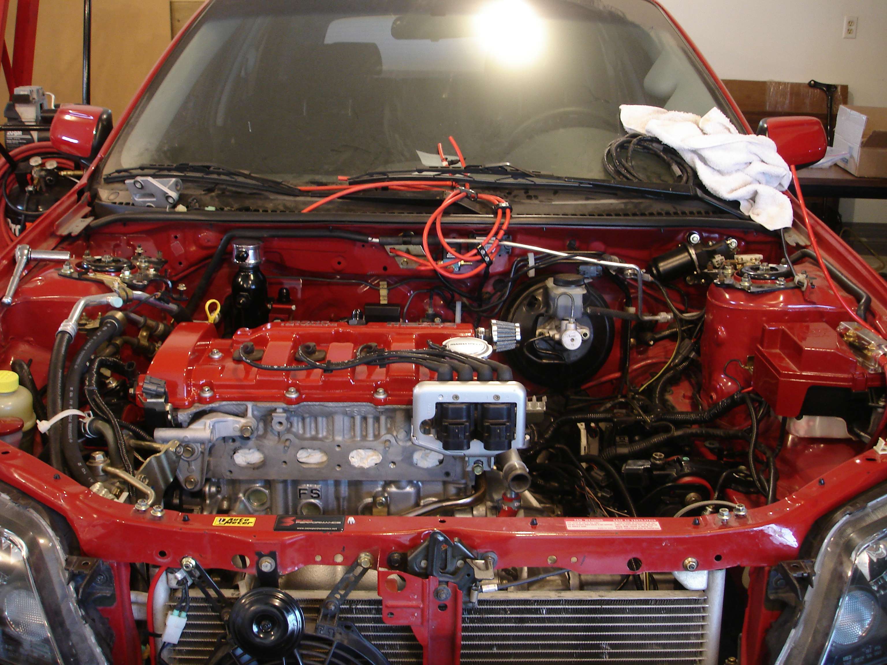
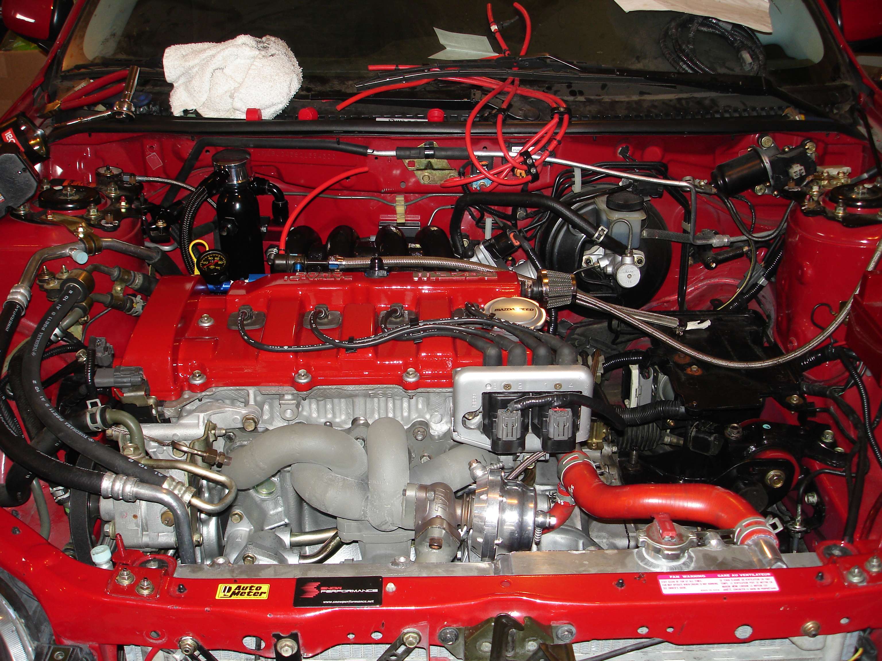
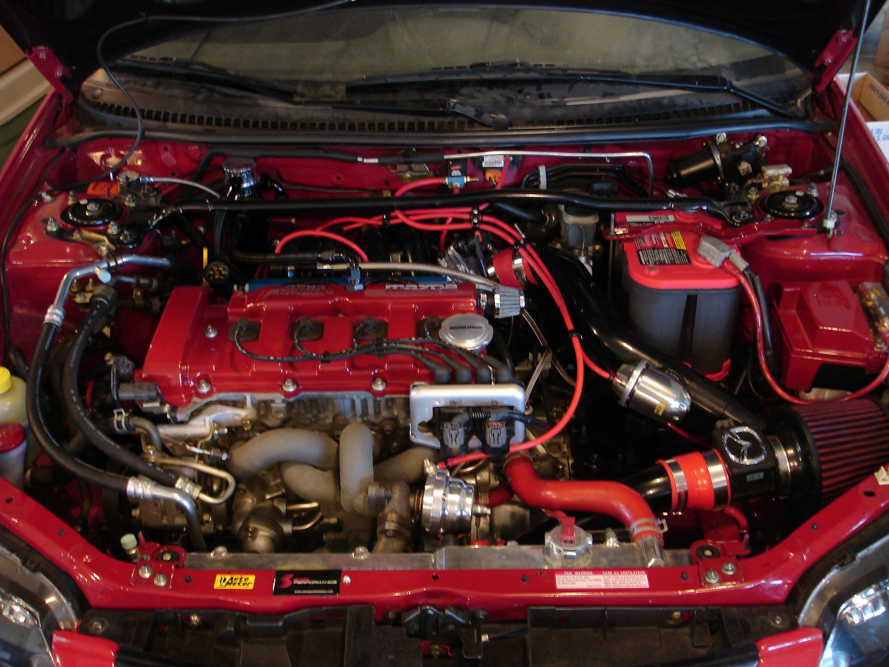
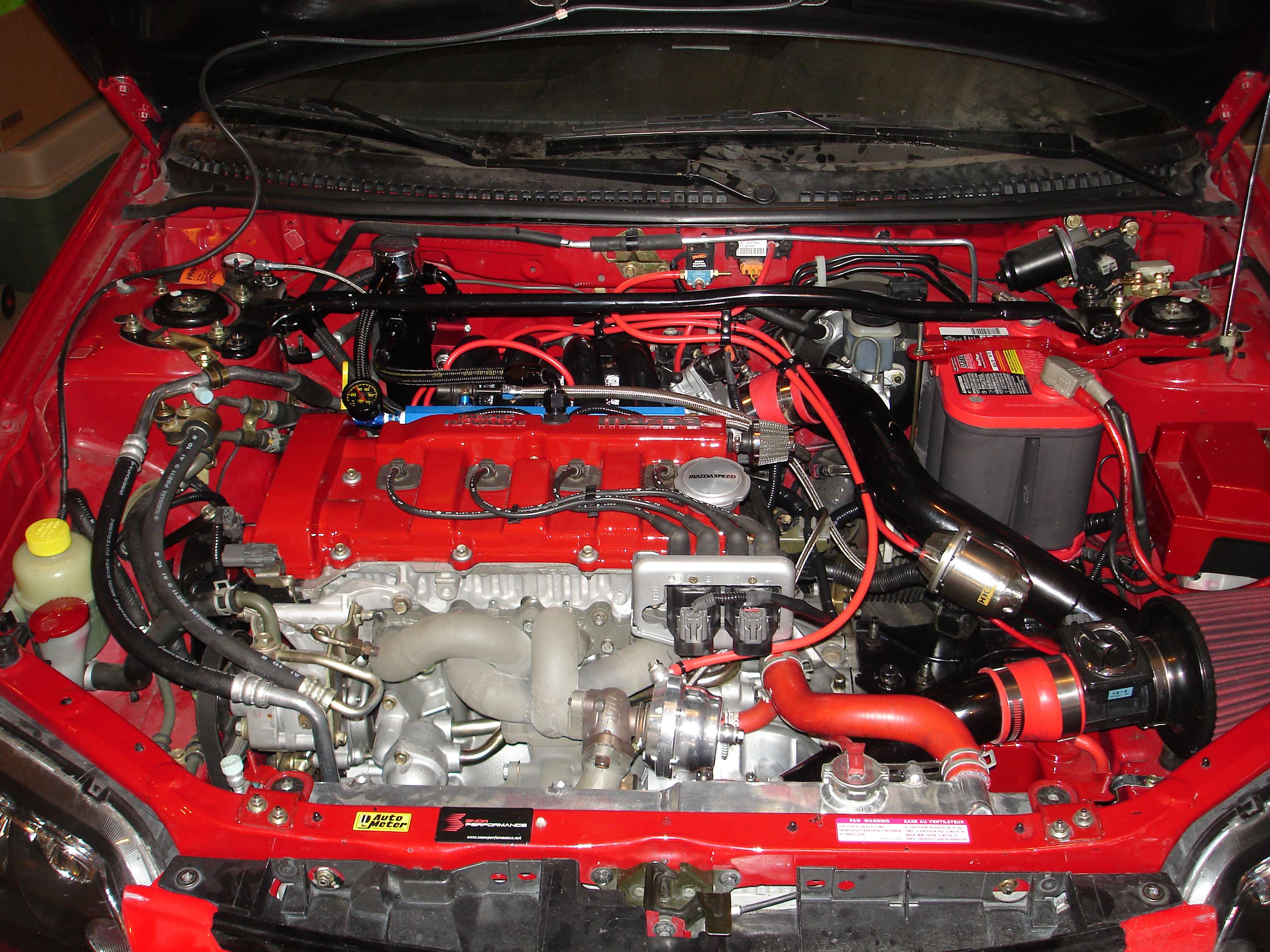
The finished product:
I've got most issues worked out now, a few remain. Oil pressure is awesome after switching to Shell Rotella 15W-40 for the remainder of the break in. Idle pressure is 25psi, up to 75psi by 4,000RPM. Mint. Had a small exhaust leak, just needed to loosen the pipe joint, wiggle it and re-tighten. I'm not happy with the idle, the IAC is almost a little too sensitive. What I may do is build another block to space it our farther from the throttle body, giving the stepper motor more room to move in there. The charging light is on. I have the stock ECU still connected for two purposes only. Regulating the alternator, and running my stock gauge cluster. Believe it or not, disconnecting the stock IAT probe will cause the charging light to come on. Why Mazda thought it was realavent to link those two systems together is beyond me, but since I actually de-pinned the ECU connector but for about 10 wires, it will be very easy to reconnect the IAT sensor. I will leave it hidden under the ECU cover in the floorboards, since it now serves no purpose other than for voltage regulation. I will post findings after, but right now voltage at idle is 13.51V with it disconnected.
Other than that, it's purring like a kitten!
Oh yeah, here's a quick video I shot. It was cut short at the end. I filmed it with my phone and recieved a call just as I was about to wrap things up. I'll make a detailed one later on, but this should keep you guys happy for now I hope!
http://www.youtube.com/watch?v=lYPP_kY2748
...
 Posting Permissions

 Quote
Quote